Implantation of gaseous chemicals into cavities formed in intermediate dielectrics layers for subsequent thermal diffusion release

Active Publication Date: 2014-09-04
QORVO US INC
View PDF9 Cites 5 Cited by
  • Summary
  • Abstract
  • Description
  • Claims
  • Application Information

AI Technical Summary

Benefits of technology

[0008]The present invention generally relates to methods for increasing the lifetime of MEMS devices by reducing the impact velocity of a switching element in the MEMS device. Rather than leaving the encapsulated MEMS device in a vacuum cavity

Problems solved by technology

Introducing gas into the cavity causes gas damping and thin film damping which reduces the final impact speed.
These devices have to switch m

Method used


Image

  • Implantation of gaseous chemicals into cavities formed in intermediate dielectrics layers for subsequent thermal diffusion release
  • Implantation of gaseous chemicals into cavities formed in intermediate dielectrics layers for subsequent thermal diffusion release
  • Implantation of gaseous chemicals into cavities formed in intermediate dielectrics layers for subsequent thermal diffusion release

Examples


Example

[0021]To facilitate understanding, identical reference numerals have been used, where possible, to designate identical elements that are common to the figures. It is contemplated that elements disclosed in one embodiment may be beneficially utilized on other embodiments without specific recitation.

DETAILED DESCRIPTION

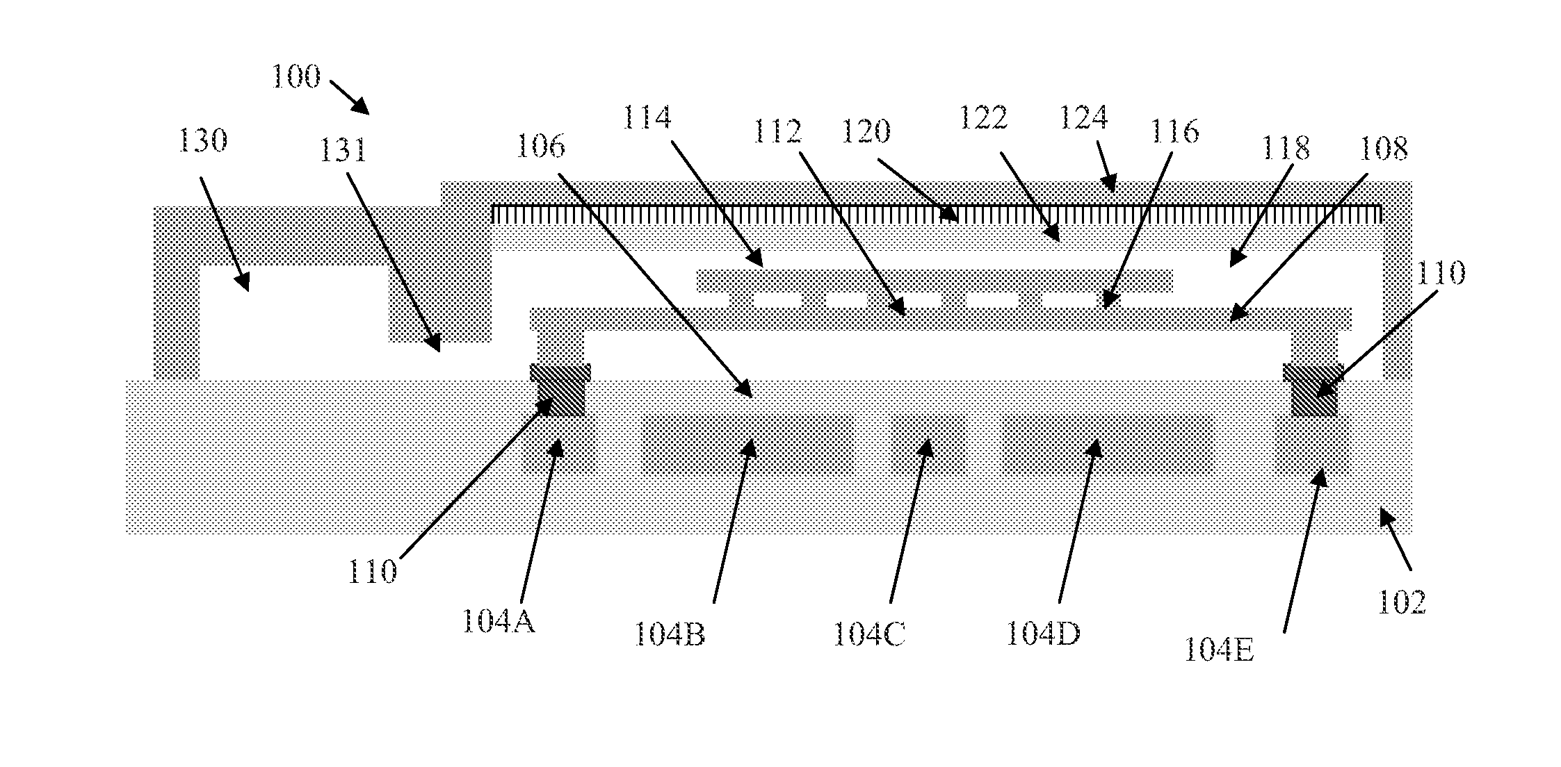
[0022]The present invention generally relates to methods for increasing the lifetime of MEMS devices by reducing the impact velocity of a switching element in the MEMS device. Rather than leaving the encapsulated MEMS device in a vacuum cavity, atoms are implanted into the cavity to introduce an inert gas into the cavity after the cavity has been sealed in the vacuum state. Introducing gas into the cavity causes gas damping and thin film damping which reduces the final impact speed.

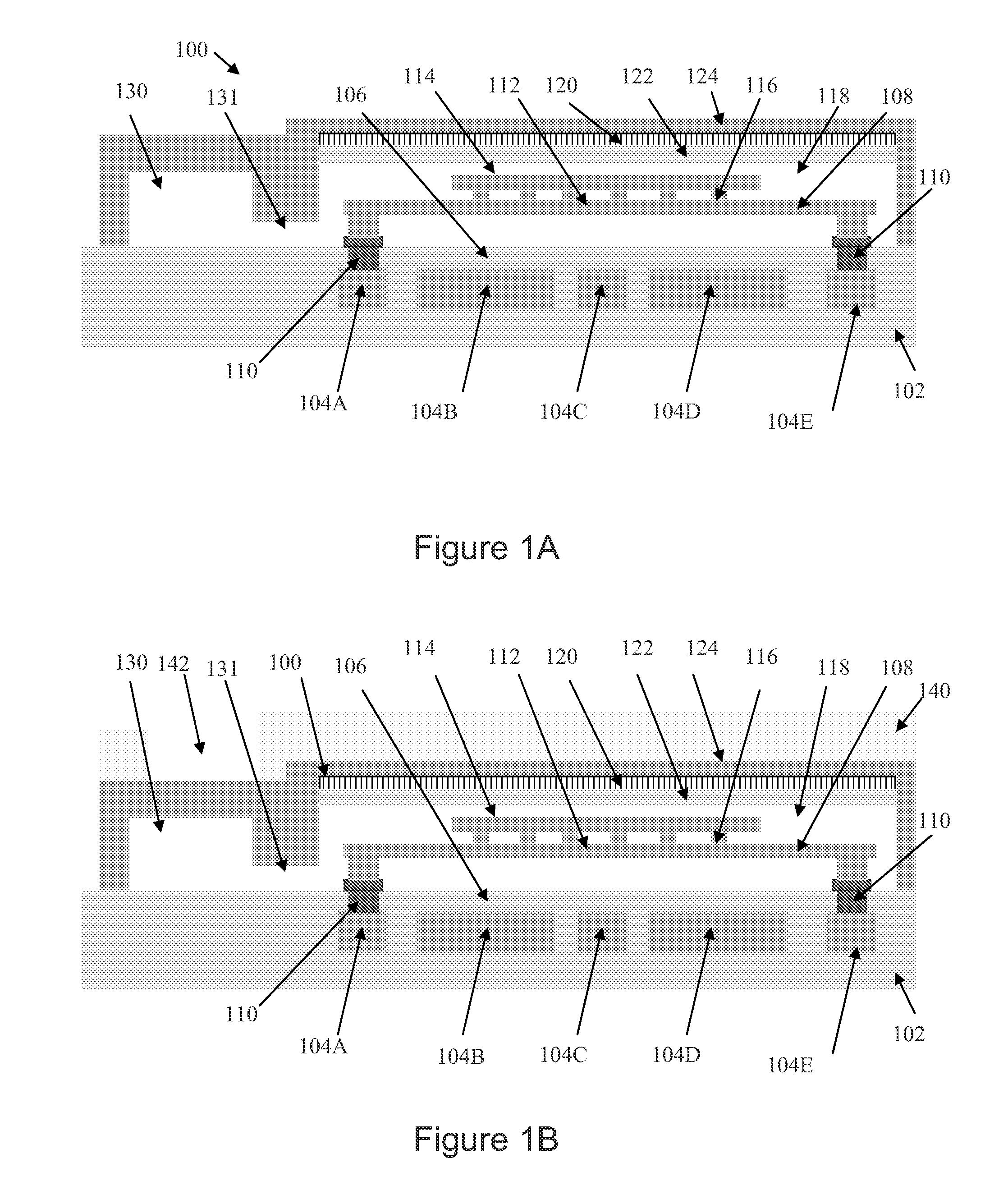
[0023]FIG. 1A shows a MEMS device 100 in the ground state according to one embodiment. The MEMS device 100 includes a substrate 102 having a plurality of electrodes 104A-104E formed therein. ...


PUM

PropertyMeasurementUnit
Areaaaaaaaaaaa

Abstract

The present invention generally relates to methods for increasing the lifetime of MEMS devices by reducing the landing velocity on switching by introducing gas into the cavity surrounding the switching element of the MEMS device. The gas is introduced using ion implantation into a cavity close to the cavity housing the switching element and connected to that cavity by a channel through which the gas can flow from one cavity to the other. The implantation energy is chosen to implant many of the atoms close to the inside roof and floor of the cavity so that on annealing those atoms diffuse into the cavity. The gas provides gas damping which reduces the kinetic energy of the switching MEMS device which then should have a longer lifetime.

Description

BACKGROUND OF THE INVENTION[0001]1. Field of the Invention[0002]Embodiments of the present invention generally relate to introducing a gas into a micro cavity to enhance the lifetime of a micro-electromechanical system (MEMS) devices.[0003]2. Description of the Related Art[0004]A digital variable capacitor (DVC) utilizing MEMS technology operates by having a switching element of the MEMS device move between a state of high capacitance and a state of low capacitance. In a state of high capacitance, the switching element is in a position adjacent an RF electrode. In a state of low capacitance, the switching element is in a position adjacent to another electrode spaced from the RF electrode, or more specifically, away from an insulating layer that is disposed on the RF electrode. The switching element may also be moved to ground whereby the switching element is adjacent neither the RF electrode nor the other electrode.[0005]During the lifetime of the MEMS device, the switching element ...

Claims


Application Information

Patent Timeline
IPC IPC(8): B81B3/00B81B7/00B81C1/00
CPCB81B3/0059B81B2203/0127B81B7/0035B81C1/00285B81C1/00293B81C1/00682B81B7/00B81C1/00H01L29/84
Inventor VAN DEN HOEK, WILLIBRORDUS GERARDUSVAN KAMPEN, ROBERTUS PETRUSKNIPE, RICHARD L.SMITH, CHARLES GORDON
Owner QORVO US INC
Why Eureka
Try Eureka