

Method for manufacturing organic electroluminescent display apparatus
- Summary
- Abstract
- Description
- Claims
- Application Information
AI Technical Summary
Benefits of technology
Problems solved by technology
Method used
Image

Examples
first embodiment
Sealing Step (First Embodiment)
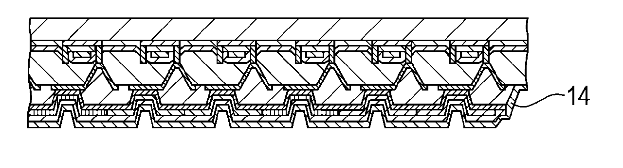
[0121]In the organic electroluminescent display apparatus manufactured by the method of the present invention, the electrode layers and the organic electroluminescent layer constituting the display apparatus can be protected from moisture and oxygen in the atmosphere using a sealing member.
[0122]For example, components other than connecting terminals are covered with a glass cap and the substrate is bonded to the glass cap with an adhesive, thereby blocking the organic electroluminescent elements constituting the sub-pixels from the outside air. Thus, the organic electroluminescent display apparatus is manufactured. Note that the organic electroluminescent elements may be blocked from the outside air by providing a protective film composed of SiN or the like instead of using such a glass cap.
[0123]Subsequently, a power supply, image signals, and driving signals are supplied from an external circuit to the manufactured organic electroluminescent display...
second embodiment
[0124]Next, a second embodiment of the present invention will be described. First, an organic electroluminescent display apparatus manufactured in this embodiment will be described.
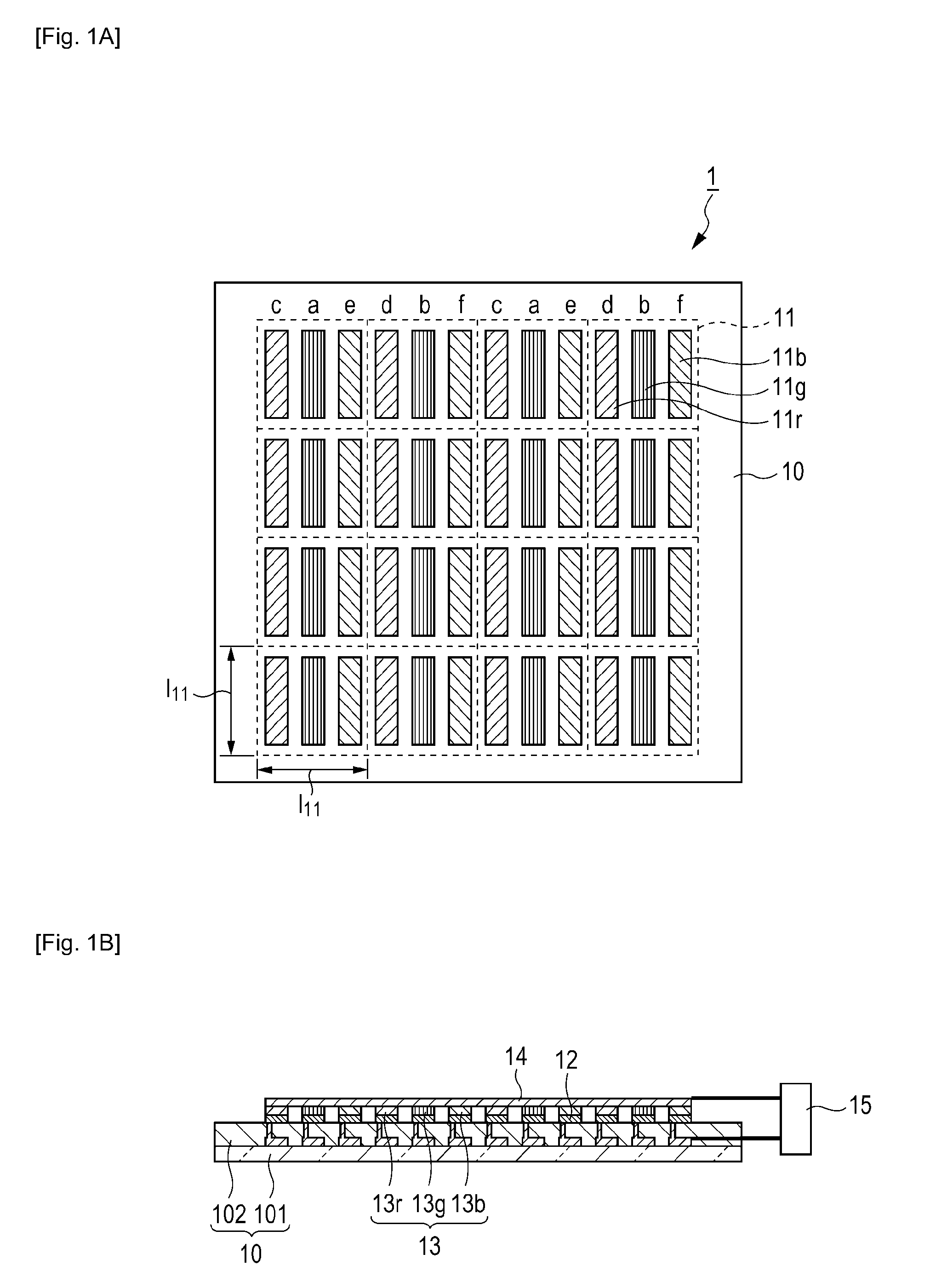
[0125]FIG. 4A is a schematic plan view showing a second example of an organic electroluminescent display apparatus manufactured by a method of the present invention. FIG. 4B is a schematic cross-sectional view of the organic electroluminescent display apparatus. Components the same as those of the organic electroluminescent display apparatus 1 shown in FIGS. 1A and 1B are assigned the same reference numerals. The difference from the first example described in the first embodiment will be mainly described below.
[0126]An organic electroluminescent display apparatus 4 shown in FIGS. 4A and 4B has an alignment pattern of sub-pixels of, from the left of a display area, RGBGRGBG. However, two G sub-pixels included in one pixel can be respectively driven by separate signals. Accordingly, the G sub-pixels can be ...
third embodiment
[0142]Next, a third embodiment of the present invention will now be described. First, an organic electroluminescent display apparatus manufactured in this embodiment will be described.
[0143]FIG. 6A is a schematic plan view showing a third example of an organic electroluminescent display apparatus manufactured by a method of the present invention. FIG. 6B is a schematic cross-sectional view of the organic electroluminescent display apparatus. Components the same as those of the organic electroluminescent display apparatus 1 shown in FIGS. 1A and 1B are assigned the same reference numerals. The difference from the first example described in the first embodiment will be mainly described below.
[0144]An organic electroluminescent display apparatus 6 shown in FIGS. 6A and 6B has an alignment pattern of sub-pixels of, from the left of the display area, (R)RGBBGRRGBBGR.
[0145]Next, this embodiment will be specifically described. In the description below, the difference from the first embodim...
PUM
 Abstract
Description
Claims
Application Information