Magnetron sputtering apparatus

Inactive Publication Date: 2010-03-11
TOHOKU UNIV +1
View PDF14 Cites 5 Cited by
  • Summary
  • Abstract
  • Description
  • Claims
  • Application Information

AI Technical Summary

Benefits of technology

[0133]In accordance with the present invention, there is provided a magnetron sputtering apparatus capable of increasing a film forming rate and preventing a local abrasion of a target to achieve uniform consum

Problems solved by technology

However, with such a configuration, magnets or fixing rods may be distorted due to repulsive or attractive forces between the magnets, or it may be difficult to move or rotate the magnets against those forces.
To elaborate, an attractive or repulsive force of about 3000 N may be generated between the magnets, thereby causing some problems.
That is, metals supporting the magnets may be deformed, or a torque of about 30 N·m may be simultaneously generated whereby a very strong m

Method used


Image

  • Magnetron sputtering apparatus
  • Magnetron sputtering apparatus
  • Magnetron sputtering apparatus

Examples


Example

[0200]A first embodiment of the present invention will be explained in detail with reference to the accompanying drawings.

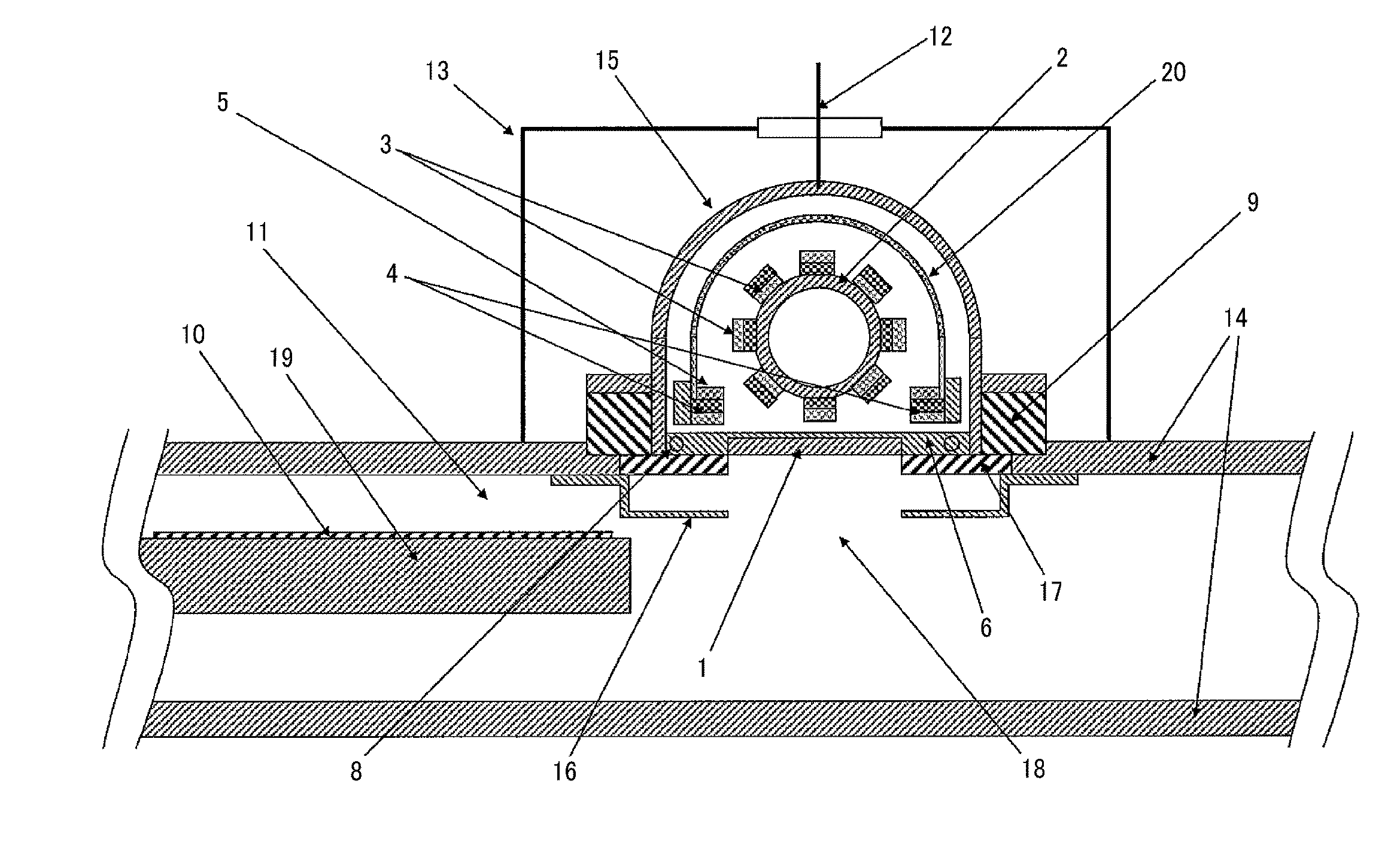
[0201]FIG. 1 is a cross sectional view illustrating a configuration of a magnetron sputtering apparatus (rotary magnet sputtering apparatus) in accordance with the first embodiment of the present invention.

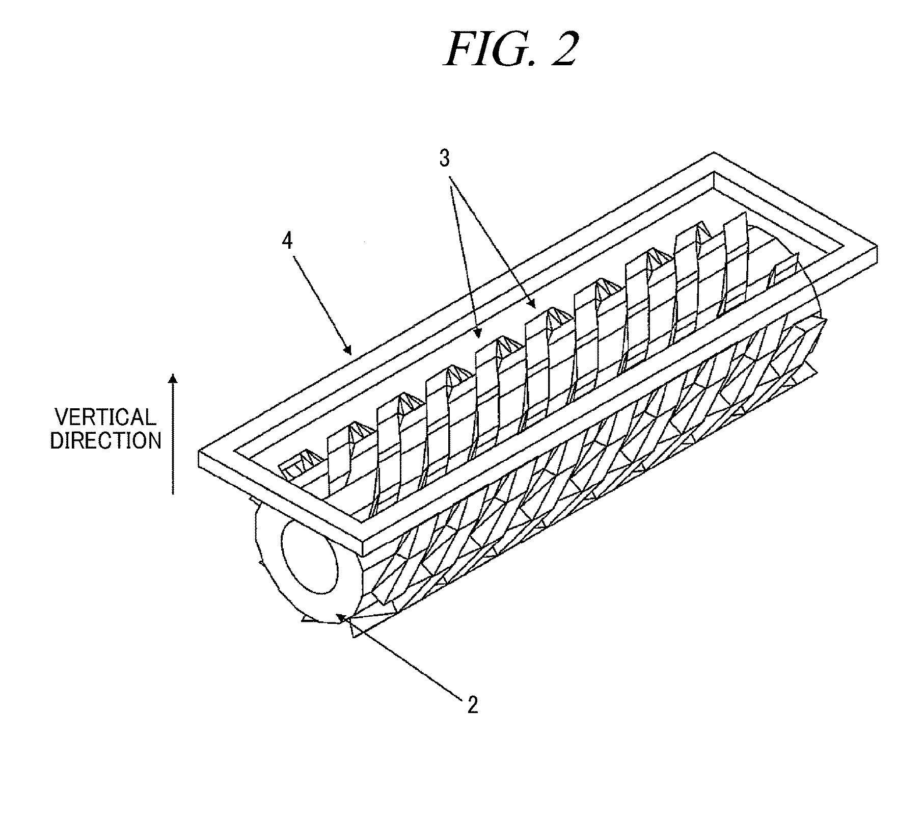
[0202]In FIG. 1, a reference numeral 1 denotes a target; 2, a column-shaped rotation shaft; 3, a plurality of plate magnet sets arranged in a spiral shape on a surface of the rotation shaft 2; 4, a stationary outer peripheral plate magnet positioned at an outer periphery; 5, an outer peripheral magnetic body positioned on the stationary outer peripheral plate magnet 4 to be opposite to the target; 6, a backing plate to which the target 1 is fixed; 15, a magnetic body configured to enclose the column-shaped rotation shaft 2 and the spiral-shaped plate magnet sets 3 except their target-facing sides; 8, a passage through which a coolant passes; 9, an insulating me...

Example

[0229]A second embodiment of the present invention will be explained in detail with reference to FIG. 12. Descriptions of the same parts as those of the aforementioned embodiment will be omitted for the simplicity of description. A magnetron sputtering apparatus in accordance with the present invention has two spirals. It can be seen from FIG. 11 that in case of two spirals, a difference between a maximum horizontal magnetic field and a minimum horizontal magnetic field becomes small. If a magnetic field in a loop is uniform, a plasma density in the loop becomes uniform, so that a uniformity of consumption of a target 1 caused by rotation of a magnet is more effectively enhanced. This is because a direction of a peripheral stationary magnet becomes nearly perpendicular to a direction of a spiral magnet. In this case, a spiral angle is about 79°. It can be seen that in order to obtain such a uniformity effectively, a spiral angle is desirably in a range of about 70° to 88° and, more ...

Example

Third Embodiment

[0232]A third embodiment of the present invention will be explained in detail with reference to the drawings. Further, descriptions of the same parts as those of the aforementioned embodiments will be omitted for the simplicity of description. A magnetron sputtering apparatus in accordance with the present invention is especially suitable to be used as a reciprocating film forming apparatus as illustrated in FIG. 9.

[0233]In FIG. 9, a reference numeral 401 denotes a processing chamber; a reference numeral 402 denotes a gate valve; a reference numeral 403 denotes a substrate to be processed; and a reference numeral 404 is a rotary magnet plasma exciting unit of the third embodiment. The length of the spiral in a direction of the axis is set to about 307 mm in the first embodiment, whereas it is set to about 270 mm in this embodiment. A frequency of plasma excitation power is set to about 13.56 MHz. However, the frequency is desirably as high as about 100 MHz in order t...


PUM

PropertyMeasurementUnit
Lengthaaaaaaaaaa
Fractionaaaaaaaaaa
Fractionaaaaaaaaaa

Abstract

Provided is a magnetron sputtering apparatus that increases an instantaneous plasma density on a target to improve a film forming rate. The magnetron sputtering apparatus includes a substrate to be processed, a target installed to face the substrate and a rotary magnet installed at a side opposite to the substrate across the target. In the magnetron sputtering apparatus, plasma loops are formed on a target surface. The plasma loops are generated, move and disappear in an axis direction of the rotary magnet according to a rotation of the rotary magnet.

Description

TECHNICAL FIELD[0001]The present invention relates to a magnetron sputtering apparatus which performs a preset surface processing on a target object such as a liquid crystal display substrate or a semiconductor substrate.BACKGROUND ART[0002]A thin film forming process for forming a thin film of a metal or an insulating material on a substrate is indispensable in the manufacture of a semiconductor device such as an IC or a liquid crystal display device. A film forming method using a sputtering apparatus is used in the thin film forming process. In this film forming method, a target made of a raw material for a thin film formation is used; and an argon gas or the like is excited into plasma by a DC high voltage or a high frequency power; and the target is activated by the gas excited into plasma and is sputtered; and then it is deposited on a target substrate.[0003]A film forming method using a magnetron sputtering apparatus is mainly employed as a sputtering film forming method. In t...

Claims


Application Information

Patent Timeline
IPC IPC(8): C23C14/35
CPCC23C14/35H01J37/3455H01J37/3405
Inventor OHMI, TADAHIROGOTO, TETSUYAMATSUOKA, TAKAAKI
Owner TOHOKU UNIV
Why Eureka
Try Eureka