
Vehicle control system

a technology of vehicle control and control system, which is applied in the direction of driver input parameters, transportation and packaging, propulsion unit arrangement, etc., can solve the problems of not always small acceleration demand after decelerating the vehicle, vehicle may not be accelerated satisfactory, and may not generate the acceleration intended by the driver

Active Publication Date: 2020-04-30
TOYOTA JIDOSHA KK
View PDF0 Cites 7 Cited by
  • Summary
  • Abstract
  • Description
  • Claims
  • Application Information

AI Technical Summary

Benefits of technology

The present invention relates to a vehicle control system that can be used in a vehicle that can be propelled in a one-pedal mode. The system can control both the driving force and the braking force by manipulating the accelerator pedal and the brake pedal. The system estimates the driver's intention to accelerate or decelerate the vehicle based on the operating speed of the pedal returned to the initial position after being released. The system adjusts the target acceleration accordingly to control the vehicle's acceleration and deceleration in line with the driver's intention without causing discomfort or shock. The system does not correct the target acceleration within the accelerating range, ensuring smooth acceleration based on the normal target acceleration.

Problems solved by technology

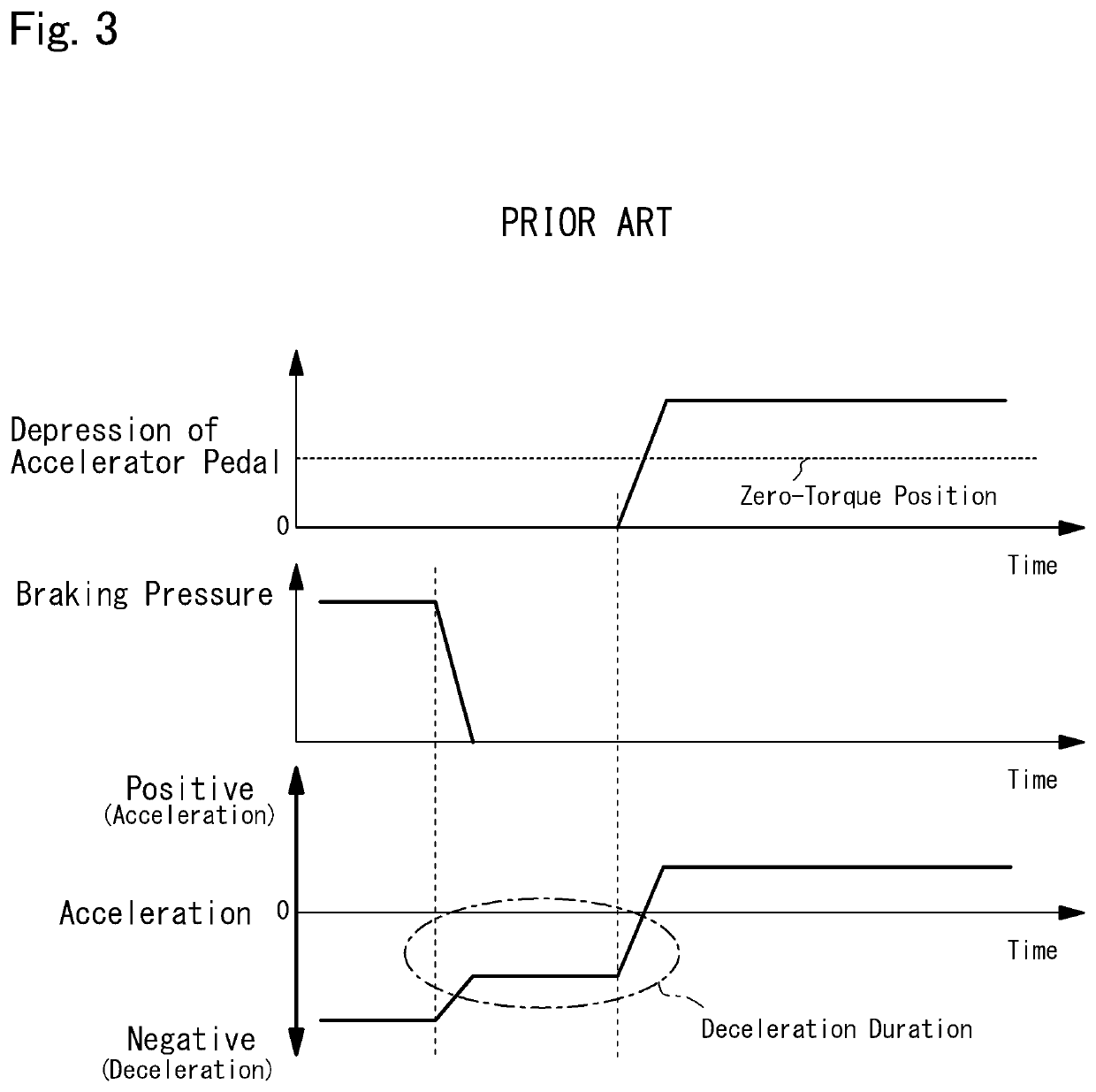
Therefore, the acceleration intended by the driver may not be generated when depressing the accelerator pedal after releasing the brake pedal.
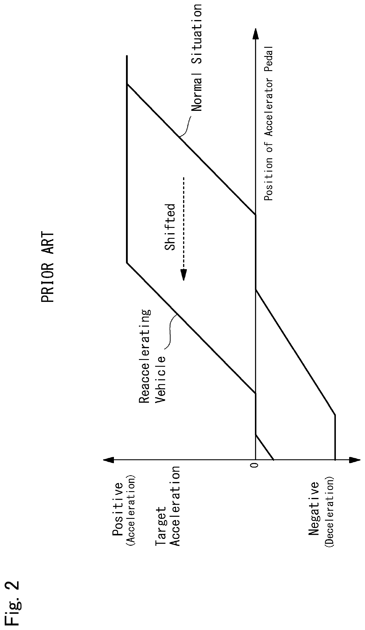
However, if the deceleration established by depressing the brake pedal is small, the acceleration demand after decelerating the vehicle may not always be small.
In this case, the vehicle may be decelerated in spite of depressing the accelerator pedal, and the vehicle may not be accelerated satisfactory.
For this reason, a shock may be generated when accelerating the vehicle by depressing the accelerator pedal after releasing the brake pedal.
In this case, therefore, the deceleration may be changed significantly stepwise thereby providing the driver with uncomfortable feeling.
In addition, the vehicle control system according to the embodiment of the present disclosure corrects the target acceleration only within the decelerating range, and does not correct the target acceleration within an accelerating range.
If such period in which none of the pedals is operated is long, the control system estimates that an intention of the driver to accelerate or decelerate the vehicle after depressing one of the pedals is weak.

Method used


Image

  • Vehicle control system
  • Vehicle control system
  • Vehicle control system

Examples


Embodiment Construction

)

[0040]Embodiments of the present invention will now be explained with reference to the accompanying drawings. Note that the embodiments shown below are merely examples of the present invention, and do not limit a scope of the present invention.

[0041]Referring now to FIG. 5, there is shown an example of a drive system of a vehicle Ve to which the control system according to the embodiment of the present disclosure is applied. The vehicle Ve illustrated in FIG. 5 comprises a prime mover (referred to as “PWR” in FIG. 1) 1, a pair of front wheels 2, a pair of rear wheels 3, an accelerator pedal 4, a brake pedal 5, a brake device (referred to as “BK” in FIG. 1) 6, a detector 7, and a controller (referred to as “ECU” in FIG. 1) 8.

[0042]The prime mover 1 generates a drive torque to establish a driving force to propel the vehicle Ve. For example, an internal combustion engine such as a gasoline engine and a diesel engine may be adopted as the prime mover 1. An output power of the engine ma...


PUM


Abstract

A vehicle control system to control acceleration in line with the driver's intention when depressing one of an accelerator pedal and a brake pedal after releasing the other one of the pedals in one-pedal mode. The vehicle control system is configured to obtain an operating speed of one of an accelerator pedal and a brake pedal returned to an initial position, set a target acceleration based on an operating amount of the other pedal depressed after releasing said one of the pedals, and increase a correction amount to correct the target acceleration if the operating speed of the returned pedal is fast.

Description

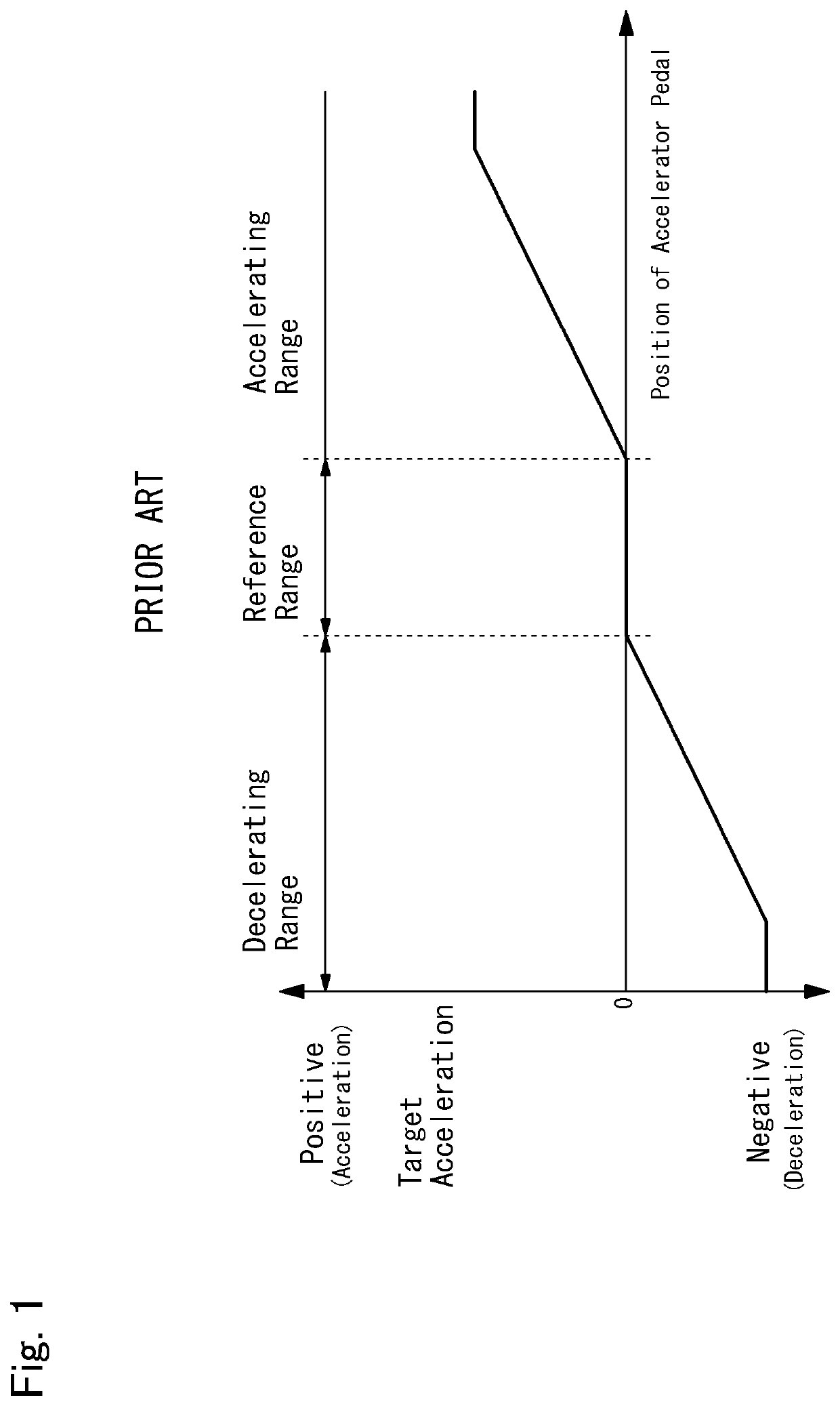
CROSS REFERENCE TO RELATED APPLICATIONS[0001]The present disclosure claims the benefit of Japanese Patent Application No. 2018-200500 filed on Oct. 25, 2018 with the Japanese Patent Office, the disclosure of which are incorporated herein by reference in its entirety.BACKGROUNDField of the Disclosure[0002]Embodiments of the present disclosure relate to the art of a vehicle control system configured to control a driving force and a braking force in response to an operation of a pedal, and more particularly, to a vehicle control system configured to propel a vehicle in a one-pedal mode in which a driving force and a braking force are controlled by manipulating one pedal.Discussion of the Related Art[0003]JP-A-2006-138266 describes an acceleration and deceleration control device for a vehicle in which acceleration and deceleration can be controlled by an accelerator pedal in one-pedal mode. As indicated in FIG. 1, according to the teachings of JP-A-2006-138266, a target acceleration is ...

Claims


Application Information

Patent Timeline
Patent Type & Authority Applications(United States)
IPC IPC(8): B60W20/19B60W10/18B60W50/10B60W30/18B60W50/06
CPCB60W10/18B60W50/06B60W30/18027B60W20/19B60W2540/106B60W2540/12B60W50/10B60K26/02B60K28/00B60T7/06B60W30/00B60W2540/10B60W30/188
Inventor SUZUKI, YUSUKE
Owner TOYOTA JIDOSHA KK
Learn More