Mold fastening device and method of controlling the mold fastening device

a fastening device and mold technology, applied in the direction of auxiliary shaping apparatus, ceramic shaping apparatus, manufacturing tools, etc., can solve the problems of ineffective utilization of the drive motor, lengthening the time for opening and closing the metal mold, etc., to enhance the operating efficiency of the mold fastening device, the output torque of the drive motor is constant, and the effect of preventing acceleration nor deceleration from lowering

Active Publication Date: 2010-05-06
TOSHIBA MASCH CO LTD
View PDF5 Cites 7 Cited by
  • Summary
  • Abstract
  • Description
  • Claims
  • Application Information

AI Technical Summary

Benefits of technology

[0016]In the mold fastening device and method of controlling the drive motor of the device, both according to this invention, the rate of increase or decrease of rotational speed of the drive motor is changed in accordance with the coupling state of the links of the toggle mechanism, i.e., the position of the cross-head. The output torque of the drive motor is therefore constant....

Problems solved by technology

Hence, the ability the drive motor has is not effectively utilized,...

Method used


Image

  • Mold fastening device and method of controlling the mold fastening device
  • Mold fastening device and method of controlling the mold fastening device
  • Mold fastening device and method of controlling the mold fastening device

Examples


Embodiment Construction

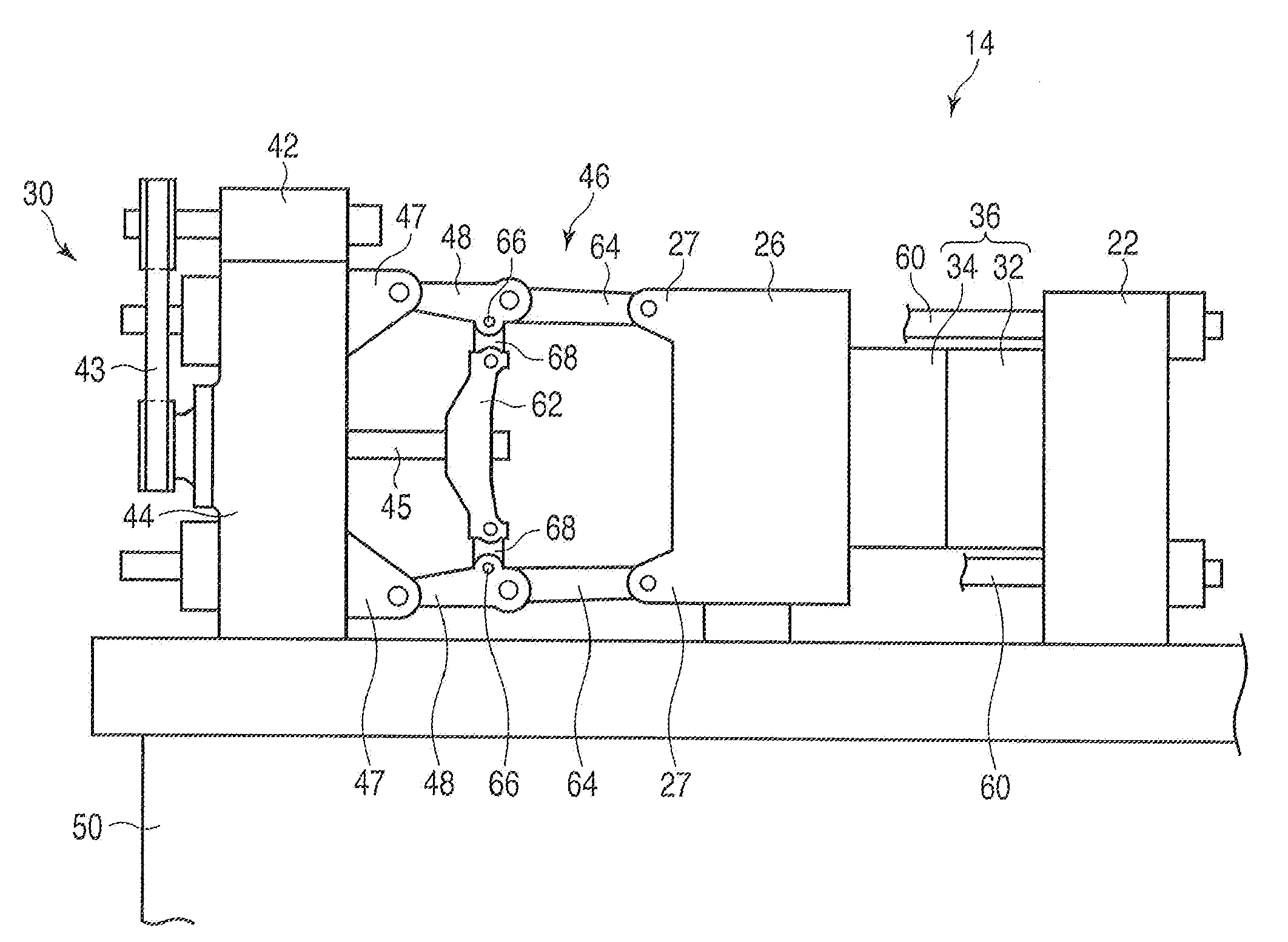
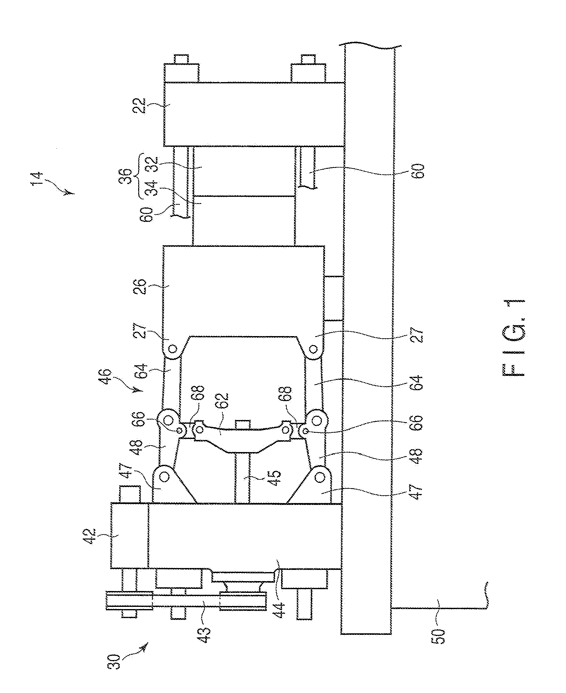
[0026]An embodiment of a mold fastening device according to this invention will be described with the accompanying drawings. FIG. 7 shows an injection molding apparatus 10 that has a mold fastening device 19.

[0027]The injection molding apparatus 10 comprises a base 50, an injection device 12, and a mold fastening device 19. The injection molding apparatus 10 has a display means 16 and an input means 18, both arranged on an almost center part of the apparatus 10.

[0028]The base 50 is almost a rectangular solid. Rails 52 are laid on the upper surface of the base 50. The rails 52 extend in the lengthwise direction of the base 50. The injection device 12 is mounted on the rails 52 and can move freely.

[0029]The injection device 12 comprises a cylinder 20, a drive mechanism (not shown), and a hopper 56. The cylinder 20 holds a screw in it. The drive mechanism can rotate the screw around its axis and move the screw back and forth in the axial direction. In the injection device 12, the drive...


PUM

PropertyMeasurementUnit
Torqueaaaaaaaaaa

Abstract

A mold fastening device has a fixed die plate, a rear plate, a movable die plate that can move back and forth, a toggle mechanism, and a drive motor that drives a cross-head. The position where the cross-head should be stopped is associated with the rate at which to accelerate the cross-head from that position or the rate at which to decelerate the cross-head to that position. The cross-head is operated at an acceleration that corresponds to that position. The drive motor is thereby driven at a constant output torque, regardless of the position of the movable die plate. Further, the time for opening and closing metal molds can be shortened.

Description

CROSS-REFERENCE TO RELATED APPLICATIONS[0001]This application is based upon and claims the benefit of priority from prior Japanese Patent Application No. 2008-285659, filed Nov. 6, 2008, the entire contents of which are incorporated herein by reference.BACKGROUND OF THE INVENTION[0002]1. Field of the Invention[0003]The present invention relates to a mold fastening device in which metal molds can be opened and closed within a short time, and to a method of controlling the drive motor in the mold fastening device.[0004]2. Description of the Related Art[0005]A mold fastening device is available, in which a toggle mechanism is provided between the rear plate and movable die plate, and an electric motor drives the toggle mechanism, thereby moving the movable die plate and locking the metal molds. In this mold fastening device, the rotational speed of the electric motor is controlled, moving the movable die plate holding the movable metal mold, thereby closing the metal molds. The movable...

Claims


Application Information

Patent Timeline
IPC IPC(8): B29C33/20
CPCB22D17/263B22D17/32B29C45/7653B29C2945/76083B29C2945/7623B29C2945/76387B29C2945/76602B29C2945/76709
Inventor TOBITA, HIDEAKITOKUYAMA, HARUMICHI
Owner TOSHIBA MASCH CO LTD
Why Eureka
Try Eureka