Solid-state water cooler

a water cooler and solid-state technology, applied in the field of water dispensers, can solve the problems of noise and vibration, add cooling costs to the building, and air circulation in and around, and achieve the effects of saving energy costs, improving operational efficiency, and consuming less power

Inactive Publication Date: 2007-03-15
ALMONT DEV
View PDF18 Cites 56 Cited by
  • Summary
  • Abstract
  • Description
  • Claims
  • Application Information

AI Technical Summary

Benefits of technology

[0005] Embodiments of the invention provide a number of technical advantages. Embodiments of the invention may include all, some, or none of these advantages. In one embodiment, a solid-state water cooler provides improved operational efficiency by consuming lower power and, thus, saves on energy bills. Such a water cooler may be compact and have no moving parts, which facilitates quiet operation and reduces wear and tear. In addition, no air movement or associated air filter is required to discharge heat into the environment.
[0006] In one embodiment, a system is disclosed that operates multiple thermoelectric coolers with an efficient standby power level that allows natural convection cooling to maintain the reservoir water at the specified set point. Such a system uses a cost-effective and efficient full power application, in conjunction with water cooling the hot sides of the thermoelectric coolers for heavy demand scenarios, which occur a small percentage of the time. In some embodiments, the system requires no forced air flow that causes noise, vibration and particulate flow within the air that might be unwarranted at many hospital, school, or manufacturing environments. In addition, a combination water filter / bubbler provides filtered water with an easy filter change.

Problems solved by technology

This approach, depending on the size of the cooling system, consumes energy, produces noise, and then dissipates this heat into an air conditioned environment, which adds cooling costs to the building.
Since this approach uses a fan to dissipate the heat to the environment, noise and vibration is generated and air is circulated in and around the water cooler that is unwarranted in many school, manufacturing, office or hospital applications.
However, prior systems only use a single thermoelectric cooler that are inefficient and can only cool applications that consume water at less than about one GPH of 50° F. water.
In addition, these designs only actively cool a small percentage of the cold reservoir making insulation a critical factor in system efficiency.

Method used


Image

  • Solid-state water cooler
  • Solid-state water cooler
  • Solid-state water cooler

Examples


Embodiment Construction

[0016] Example embodiments of the present invention and their advantages are best understood by referring now to FIGS. 1 through 7 of the drawings.

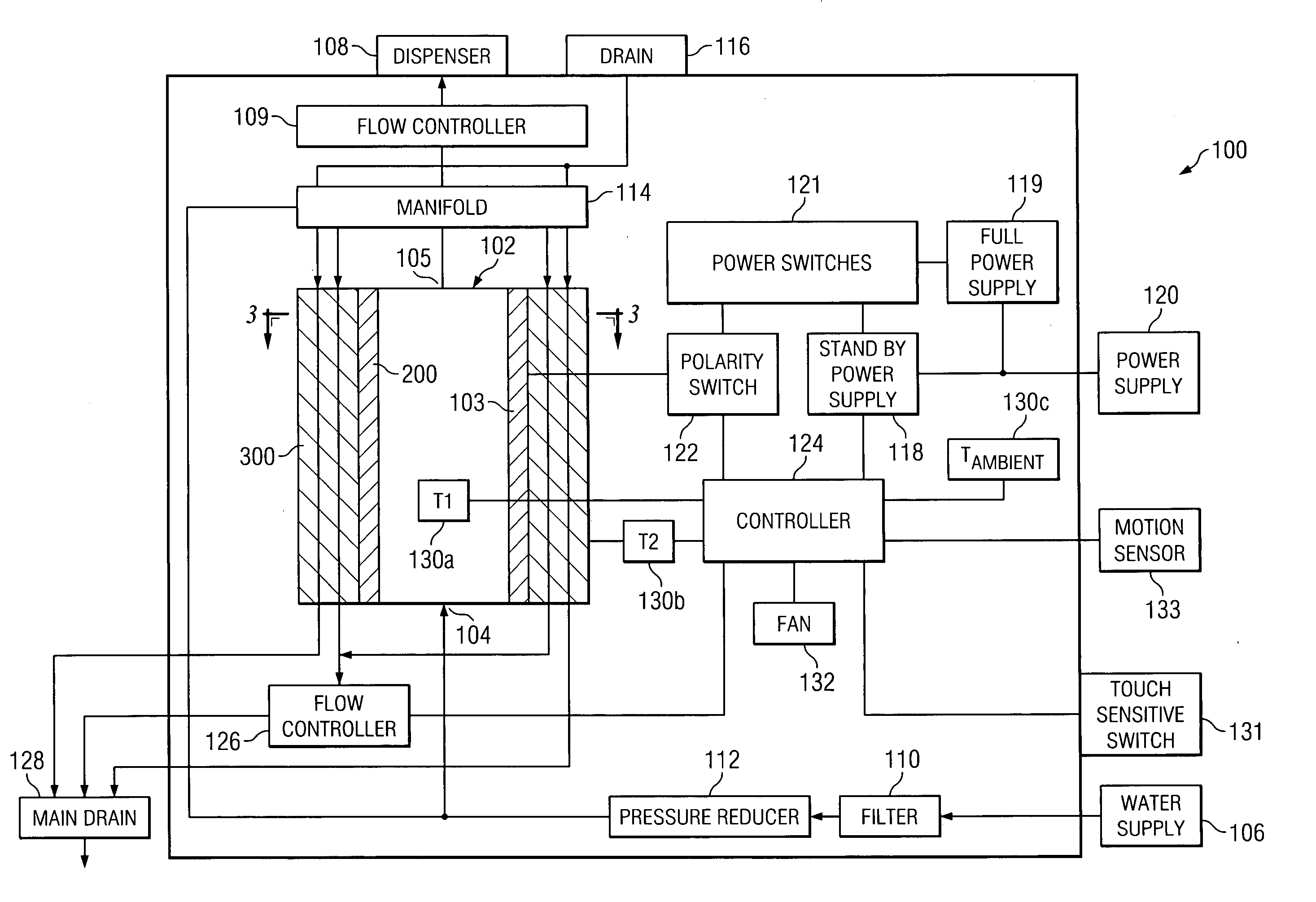
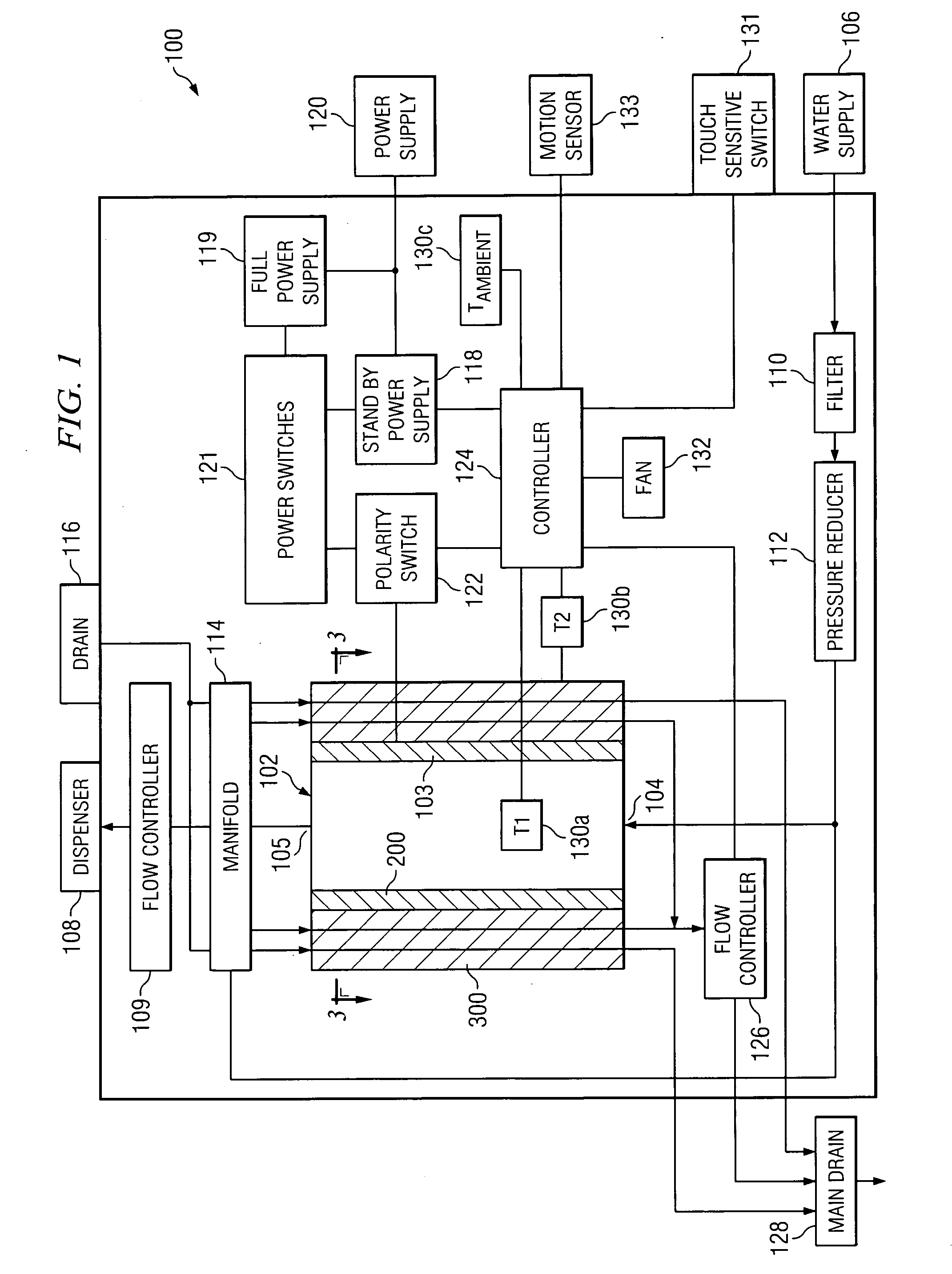
[0017]FIG. 1 is a schematic of a solid state water cooler 100 according to one embodiment of the invention. The present invention as described herein is applicable for any suitable water cooler, such as a pressurized water dispenser, a point-of-use water dispenser, a bottle water dispenser, and other devices that store and utilize cooled water. In the illustrated embodiment, water cooler 100 includes a water reservoir 102 having an inlet 104, an outlet 105, and a main body 103. Water reservoir 102 receives water from a water supply 106 and is dispensed via a dispenser 108 when a user desires water.

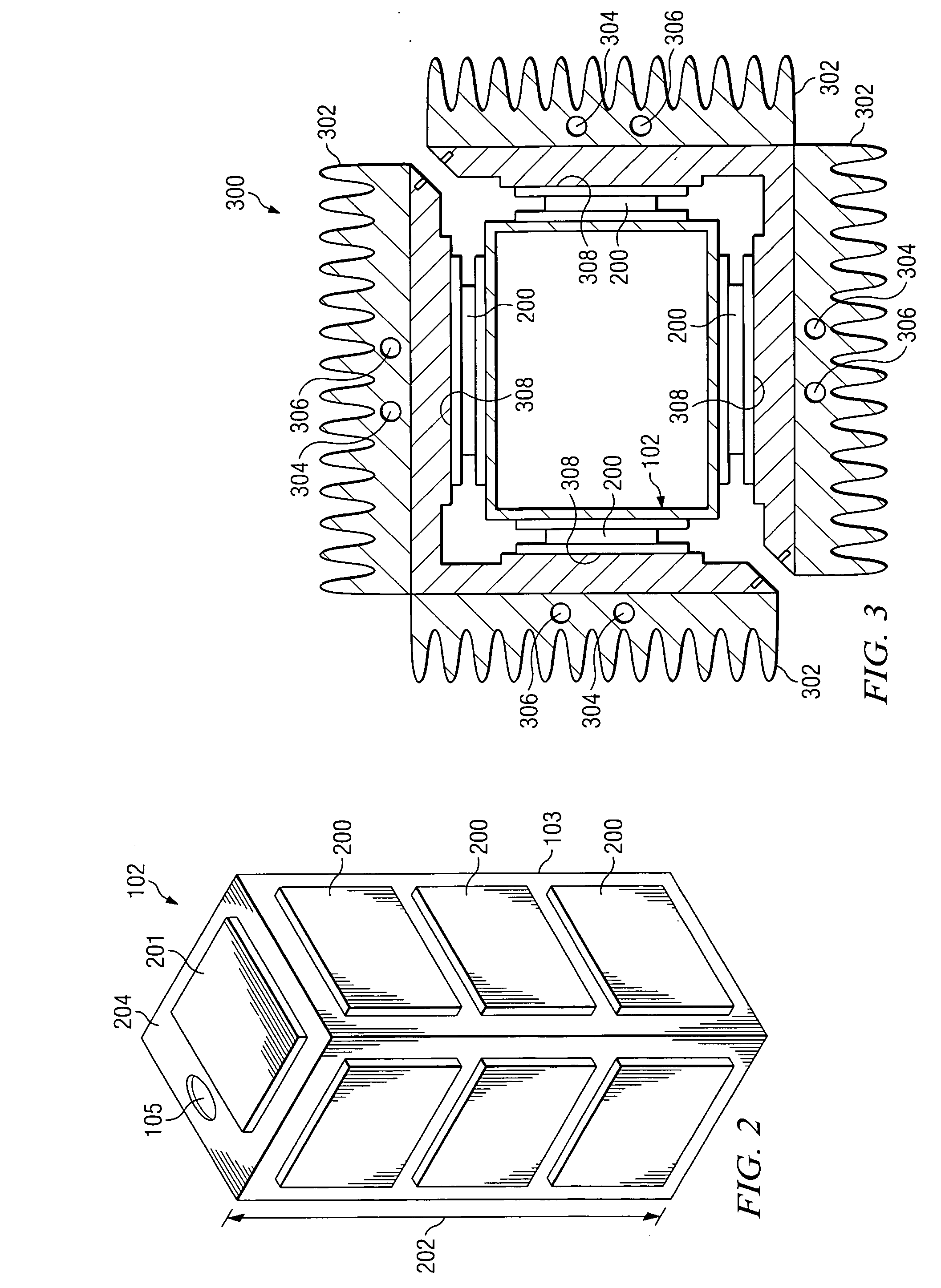
[0018] According to the teachings of one embodiment of the invention, water reservoir 102 has a plurality of thermoelectric coolers 200 disposed about a perimeter of main body 103 that are operable to control the temperature of the water insid...


PUM


Abstract

In one embodiment of the invention, a system for controlling the temperature of water in a water cooler includes a water reservoir having an inlet, an outlet, and a main body, a water supply coupled to the inlet and operable to deliver water to the water reservoir, a bubbler coupled to the outlet and operable to dispense at least some of the water from the water reservoir, and a plurality of thermoelectric coolers disposed about a perimeter of the main body and operable to control the temperature of the water inside the water reservoir.

Description

BACKGROUND OF THE INVENTION [0001] There are four basic types of water or drink dispensers: bottled water dispensers, point-of-use dispensers, pressurized water dispensers and soft drink fountains. Bottled water dispensers manually replace a bottle to supply the water. Point-of-use dispensers are freestanding appliances that use line pressure activated by a float switch to maintain a water level. Pressurized water dispensers, also know as refrigerated water fountains, are typically installed in non-residential buildings and are purchased at the time of construction. [0002] Current designs for the above dispensers use small compressor-based cooling systems that dissipate the heat to ambient via forced air. An evaporator cools a reservoir and the condenser / fan arrangement dissipates the heat. This approach, depending on the size of the cooling system, consumes energy, produces noise, and then dissipates this heat into an air conditioned environment, which adds cooling costs to the bui...

Claims


Application Information

Patent Timeline
Patent Type & Authority Applications(United States)
IPC IPC(8): F25B21/02B67D5/62B67D7/80
CPCB67D1/0869F25B21/04F25B2321/0251F25D2700/16F25D31/002F25D2700/04F25D2700/14F25B2700/2107
Inventor DE VILBISS, ROGER S.
Owner ALMONT DEV
Why Eureka
Try Eureka