Driving apparatus for hybrid vehicle

a hybrid vehicle and driving apparatus technology, applied in the direction of engine-driven generators, transportation and packaging, transportation, etc., can solve the problem that energy always passes through the electrical system and degrades efficiency, and achieve the effect of improving operation efficiency and high ratio

Inactive Publication Date: 2011-12-08
HONDA MOTOR CO LTD
View PDF0 Cites 59 Cited by
  • Summary
  • Abstract
  • Description
  • Claims
  • Application Information

AI Technical Summary

Benefits of technology

[0006]An object of this invention is therefore to overcome the foregoing drawback by providing a driving apparatus for a hybrid vehicle having an internal combustion engine and at least one electric rotating machine, which apparatus can make a vehicle run only with the engine, while improving the operation efficiency on the high ratio side.

Problems solved by technology

In the above technique, when the vehicle runs, the second rotating machine needs to be operated as a generator while the first rotating machine needs to be operated as an electric motor all the time, so that this configuration that the energy always passes through the electrical system degrades the efficiency.

Method used


Image

  • Driving apparatus for hybrid vehicle
  • Driving apparatus for hybrid vehicle
  • Driving apparatus for hybrid vehicle

Examples


first embodiment

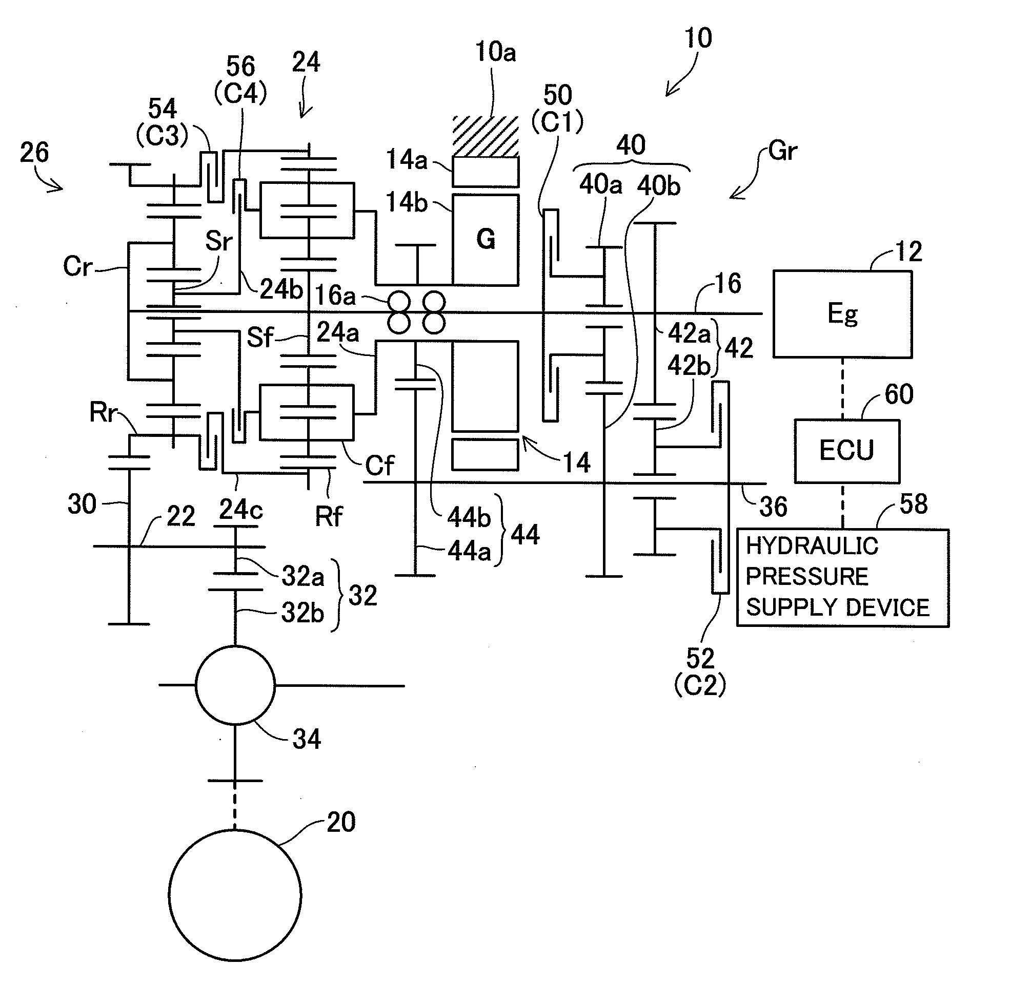
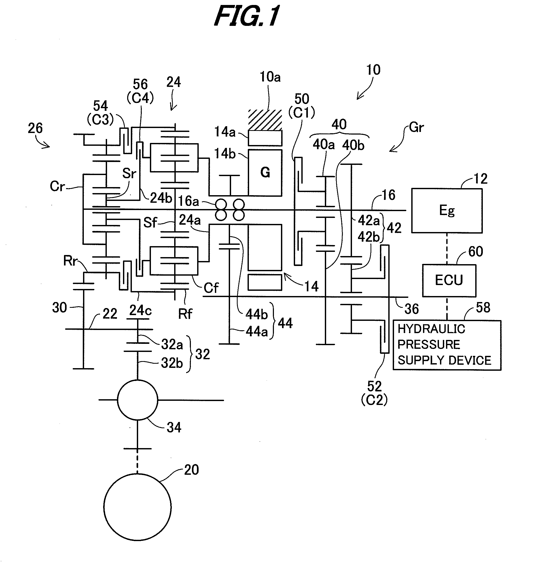
[0028]FIG. 1 is an overall view schematically showing a driving apparatus for a hybrid vehicle according to the invention;

[0029]In FIG. 1, symbol 10 indicates the driving apparatus for the hybrid vehicle. The apparatus 10 comprises an internal combustion engine 12, at least one electric rotating machine 14, an input shaft 16 connected to the engine 12, an output shaft 22 connected to a driven wheel 20, and a first planetary gear mechanism 24 and second planetary gear mechanism 26 that are installed between the input shaft 16 and the output shaft 22. The first planetary gear mechanism 24 is positioned on the upstream (front) side in the input from the engine 12, and the second planetary gear mechanism 26 on the downstream (rear) side. The apparatus 10 is mounted on the hybrid vehicle (not shown).

[0030]The engine (indicated by “Eg” in FIG. 1) 12 comprises a spark-ignition, gasoline engine (or a compression-ignition, diesel engine that runs on light oil), in which the air-fuel mixture ...

second embodiment

[0079]FIG. 4 is an overall view similar to FIG. 1, but schematically showing a driving apparatus for a hybrid vehicle according to the invention.

[0080]In the second embodiment, constituent elements corresponding to those of the first embodiment are assigned by the same reference symbols as those in the first embodiment and will not be explained.

[0081]The explanation will be made with focus on points of difference from the first embodiment. In the second embodiment, there is provided a brake (B1) 64 for engaging the carrier Cf of the first planetary gear mechanism 24, more exactly the connection member 24a thereof to the apparatus housing 10a.

[0082]Further, in addition to the first motor / generator 14, a second motor / generator (also electric rotating machine; indicated by “M”) 66 is installed to be connected to the output shaft 22.

[0083]Similarly to the first motor / generator 14, the second motor / generator 66 comprises a motor / generator constituted as a brushless AC synchronous motor,...

third embodiment

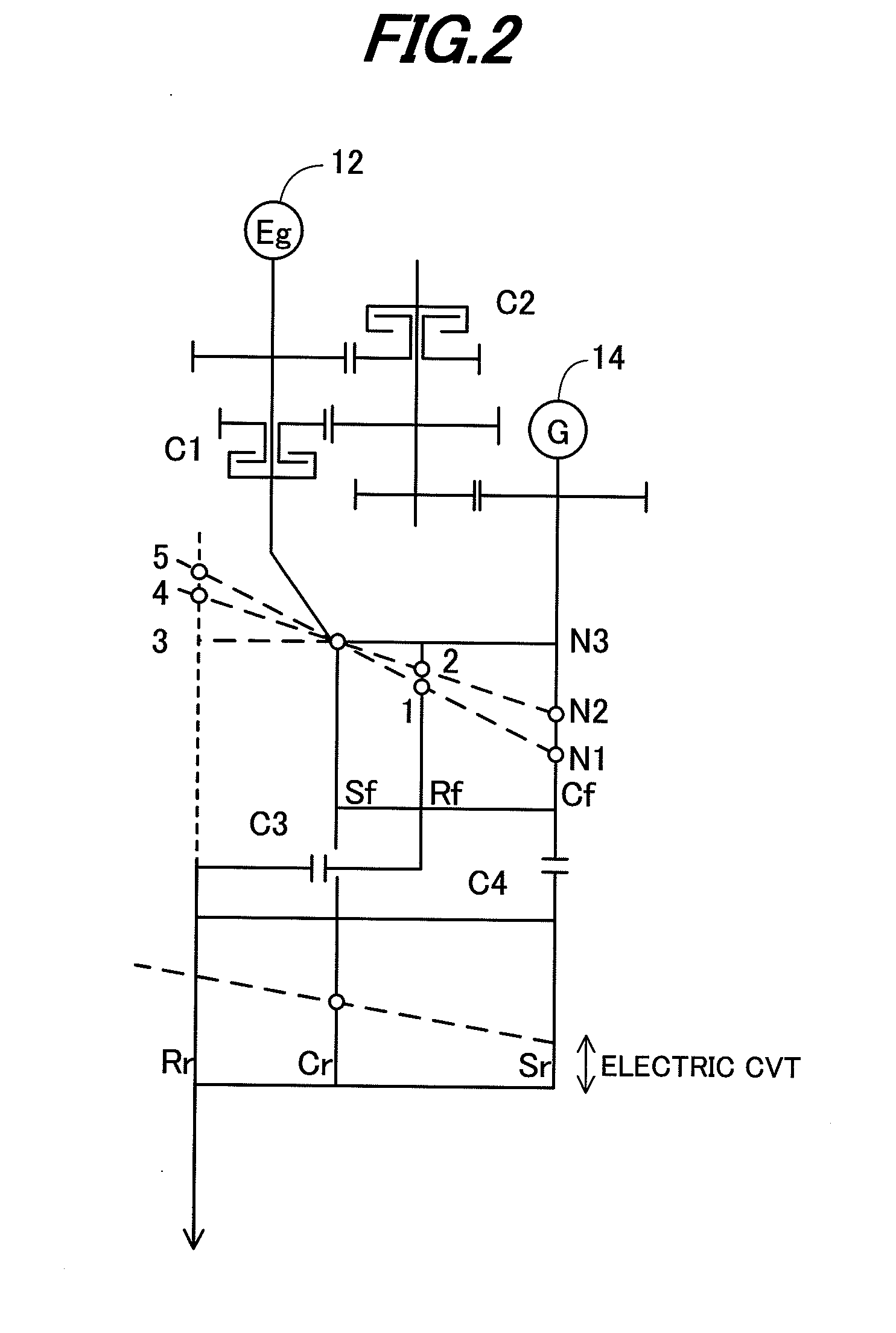
[0117]FIG. 15 is a velocity diagram of the first and second planetary gear mechanisms 24, 26, etc., of the apparatus 10 and FIG. 16 is a table showing engagement of clutches used for establishing gear positions.

[0118]As can be seen in FIG. 16, when the third and fourth clutches (C3, C4) 54, 56 are engaged so that the vehicle runs with the first motor / generator 14 (or the first and second motor / generators 14, 66) in the EV running mode, upon releasing the fifth clutch (C5) 70, it becomes possible to prevent the engine 12 from being dragged (acting as load), thereby reducing the power consumption.

[0119]As shown in FIG. 15, since the vehicle running with both the first and second motor / generators 14, 66 are made possible at the time of vehicle starting at the EV running mode and the like, the motor size can be made compact, similarly to the second embodiment.

[0120]FIG. 17 is a velocity diagram similar to FIG. 12, but showing the operation of the EV travel with the second and third spe...


PUM


Abstract

In a hybrid vehicle driving apparatus having an input shaft connected to an engine, an output shaft connected to wheels, a first planetary gear mechanism whose sun gear is connected to the input shaft, a second planetary gear mechanism whose carrier is connected to the input shaft, a mechanism reducing rotation speed of the input shaft and transmit to the first planetary gear mechanism carrier, a clutch connecting/disconnecting the first planetary gear mechanism carrier and the second planetary gear mechanism sun gear, and a clutch connecting/disconnecting ring gears of the first and second planetary gear mechanisms, the second planetary gear mechanism ring gear is connected to the output shaft and an electric rotating machine is connected to the first planetary gear mechanism carrier, thereby enabling to make a vehicle run only with the engine, while improving the operation efficiency on the high ratio side.

Description

BACKGROUND OF THE INVENTION[0001]1. Technical Field[0002]This invention relates to a driving apparatus for a hybrid vehicle.[0003]2. Background Art[0004]A driving apparatus for a hybrid vehicle proposed by Japanese Patent No. 3099721 is known. The technique of the reference is configured to have an internal combusting engine and first and second electric rotating machines, and the first rotating machine or the first rotating machine and engine is / are used as a prime mover(s) of the vehicle, while the second rotating machine is driven by the engine to generate electric power.SUMMARY OF INVENTION[0005]In the above technique, when the vehicle runs, the second rotating machine needs to be operated as a generator while the first rotating machine needs to be operated as an electric motor all the time, so that this configuration that the energy always passes through the electrical system degrades the efficiency. Further, since the driving efficiency thereof lowers as the second rotating ma...

Claims


Application Information

Patent Timeline
Patent Type & Authority Applications(United States)
IPC IPC(8): F16H3/72F16H3/46B60L50/16
CPCB60K6/365B60K6/445F16H3/725F16H37/04Y02T10/6239F16H2200/0056F16H2200/2007F16H2200/2043F16H2200/2046F16H2200/0047Y02T10/62
Inventor KUROKAWA, TAKUYA
Owner HONDA MOTOR CO LTD
Why Eureka
Try Eureka