Four-pitch wire twisting machine capable of realizing continuous production

A stranding machine and stranding technology, which is applied in the field of stranding and cabling equipment, can solve the problems of reduced stranding efficiency, increased energy consumption, and inability to produce on-line, so as to reduce production costs, increase economic benefits, and improve stranding efficiency. efficiency effect

Inactive Publication Date: 2009-12-09
向继光
View PDF0 Cites 26 Cited by
  • Summary
  • Abstract
  • Description
  • Claims
  • Application Information

AI Technical Summary

Problems solved by technology

[0006] (2) Due to the larger structure of the twisting bow, the fuselage of the twisting machine will also be lengthened, so that the equipment has to be enlarged and the manufacturing cost of the twisting machine will be increased.
[0007] (3) Due to the increase in the size of the twisted bow, the speed of the twisted wire will decrease under the same motor power drive, resulting in a decrease in the efficiency of the twisted wire and an increase in power loss. The previous speed value requires the selection of a high-power motor, which greatly increases energy consumption
[0008] (4) The take-up spools of the above-mentioned twisted-pair machines are all located in the twisting mechanism, and the twisted-pair machine can only complete the twisting process, and cannot directly transport the twisted cables to the next extrusion process, that is, only Stand-alone use, cannot be produced online, and cannot realize the continuous production process of the wire
[0009] (5) For the pair of twisted bows in the above-mentioned twisted pair machine, the incoming twisted bow plays the role of twisted wire, and the counterweight twisted bow only plays the role of counterweight, which has no effect on the twisted wire forming of the cable and cannot be fully utilized. The role of machine parts

Method used


Image

  • Four-pitch wire twisting machine capable of realizing continuous production
  • Four-pitch wire twisting machine capable of realizing continuous production
  • Four-pitch wire twisting machine capable of realizing continuous production

Examples


Embodiment 1

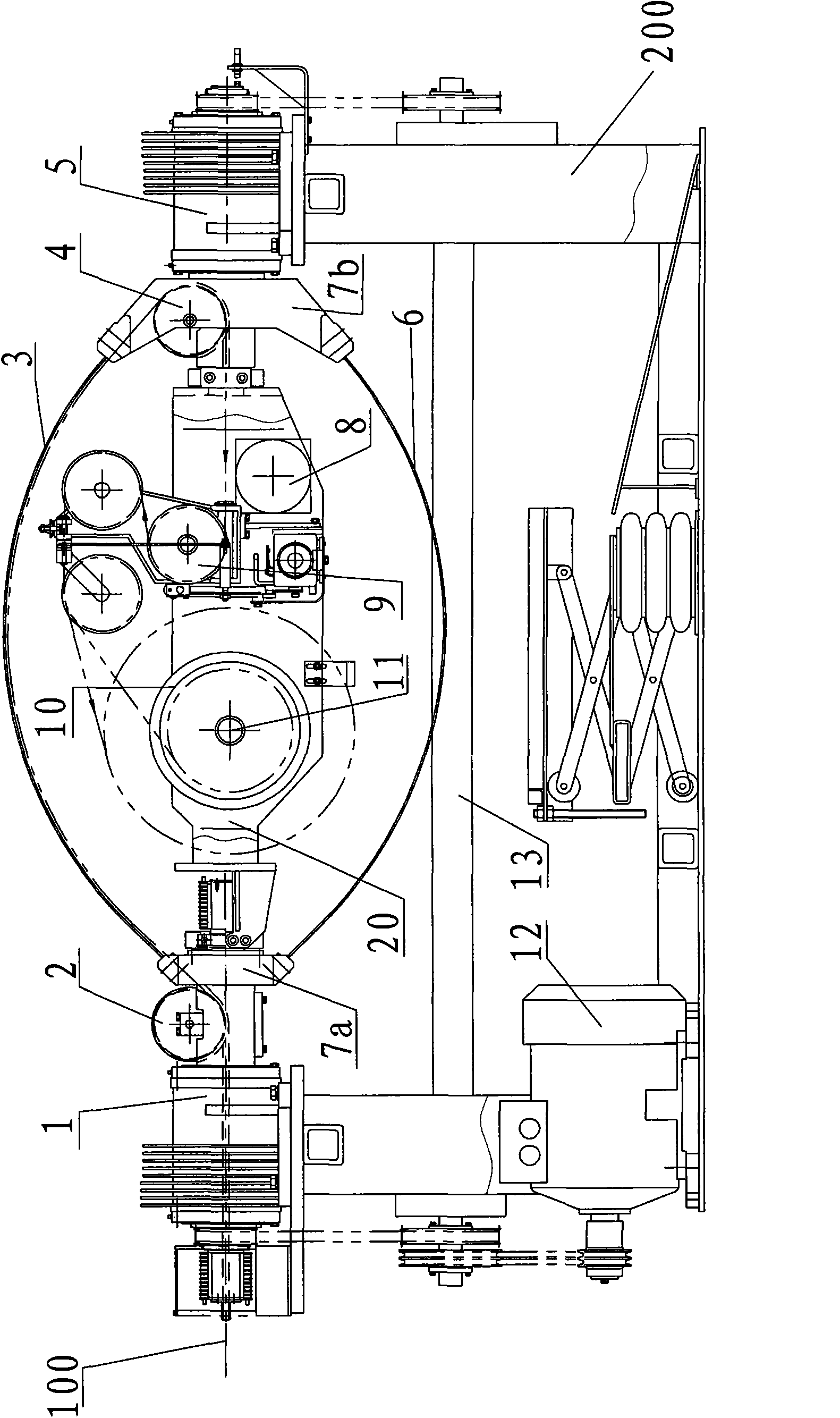
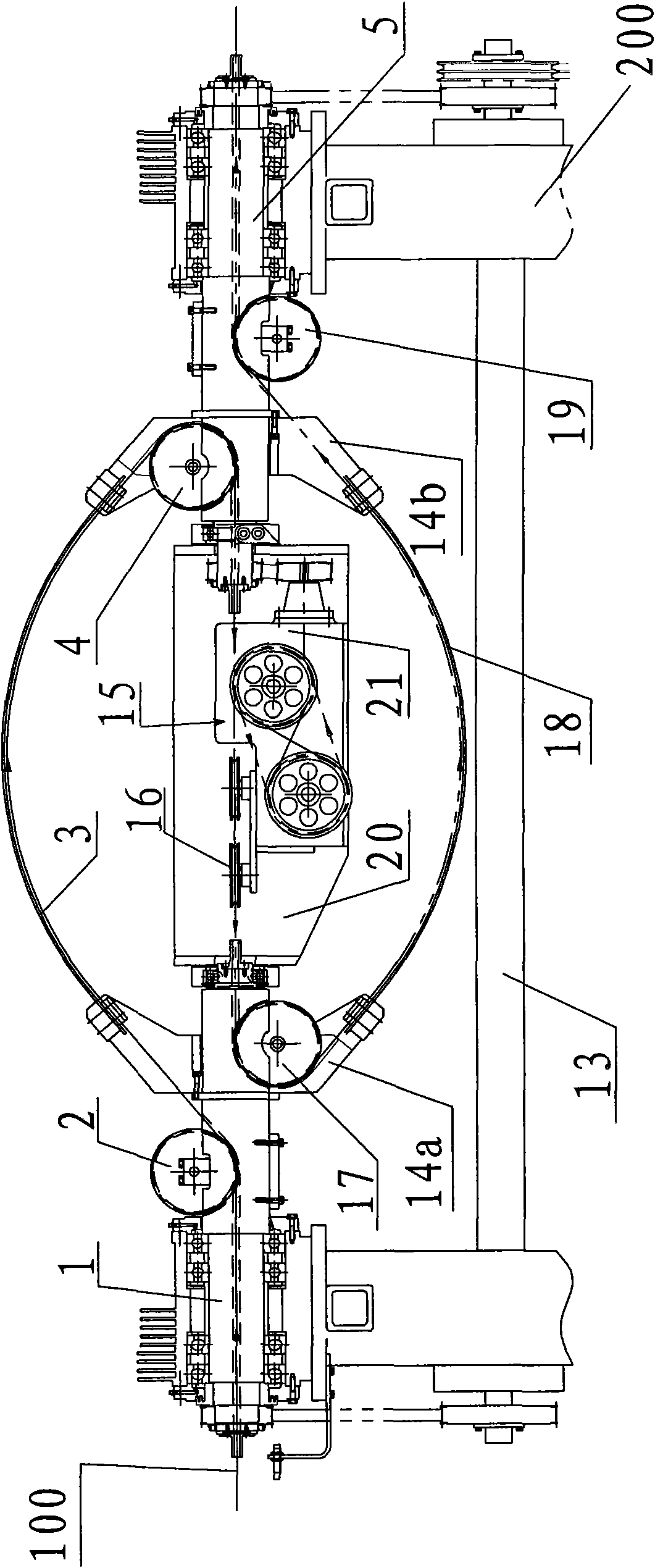
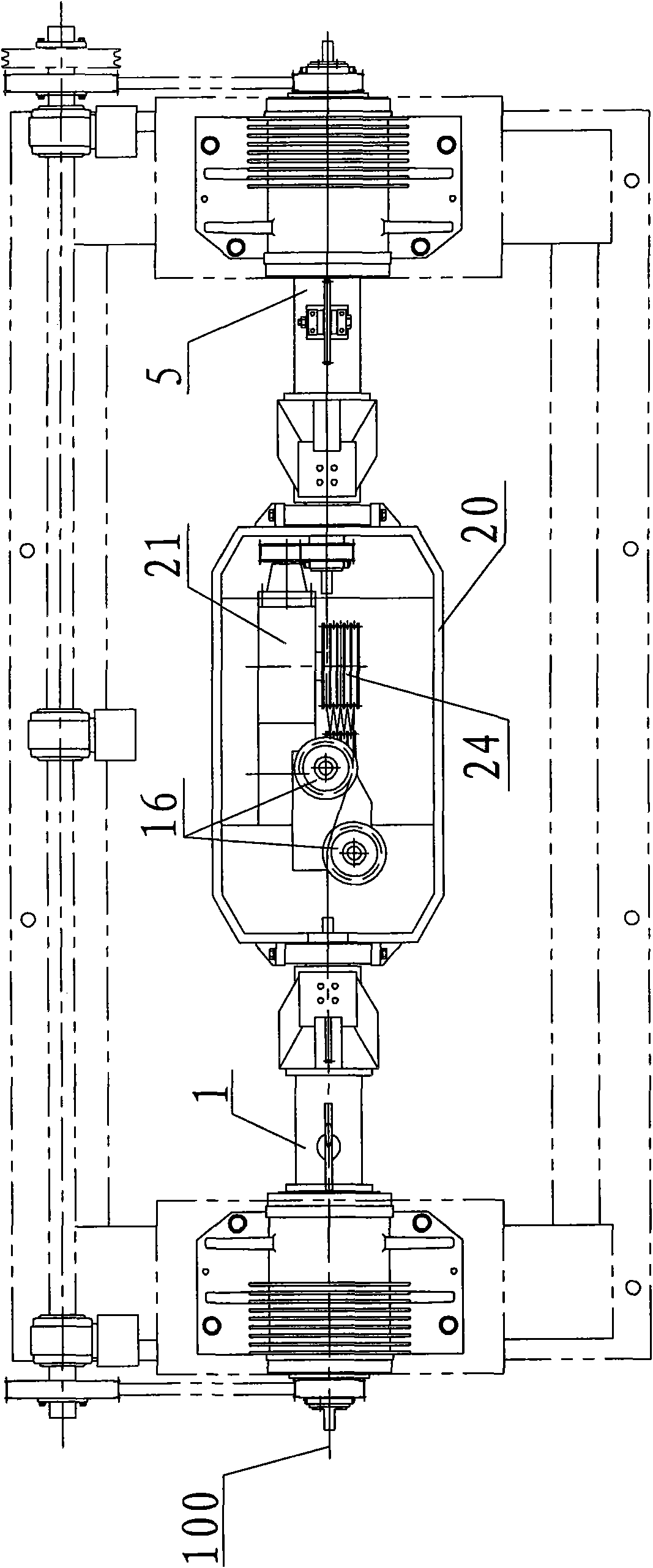
[0040] like Figure 2 to Figure 4 A four-pitch stranding machine that can realize continuous production is shown, which includes a fuselage 200, a drive mechanism, a cradle 20, an incoming wire spindle 1, an outgoing wire spindle 5, two twisting bow supports, a pair of twisting bows, The first strand guide wheel 2, the second strand guide wheel 4 and the traction device, wherein the drive mechanism is made of a motor and a transmission shaft 13, and the transmission shaft 13 is installed on the fuselage, which is connected with the motor by a transmission belt, and is driven by the motor. It is driven to rotate, and the incoming line main shaft 1 and the outgoing line main shaft 5 are respectively connected to the transmission shaft 13 through the synchronous belt, and the transmission shaft 13 drives the two to rotate synchronously. At the ends of the wire spindle and the outlet spindle, a pair of twisted bows are symmetrically arranged on the two twisted bow supports, and th...

Embodiment 2

[0048] Embodiment two of the four-pitch stranding machine of the present invention is as Figure 5 As shown, the difference from Embodiment 1 is that it is also equipped with a take-up and discharge device, which is located outside the twisting mechanism of the four-pitch twisting machine, and the conductor or core wire 100 is drawn from the fourth strand guide wheel 19 After being exported, it directly enters the wire take-up device to wind up the conductor or core wire 100. The wire take-up device includes a tension frame 25, a wire arrangement mechanism 26 and a wire take-up device 27. The tension frame 25 is equipped with a plurality of height-adjustable wire take-up devices. The tension wheel 25a with different speeds varies slightly. The wire arranging mechanism 26 is provided with a polished rod or a screw rod for arranging the wires. The wire take-up device 27 is equipped with a take-up spool 27a. , after passing through the cable arrangement mechanism, it is wound on ...

Embodiment 3

[0050] Embodiment three of the four-pitch stranding machine of the present invention is as Image 6 As shown, different from Embodiment 2, this embodiment does not have a take-up device, that is, the whole stranding machine does not have a take-up spool, and the twisted cable passes through the storage wheel of the storage rack or the tension frame 25 or The tension wheel 25a is then directly transported to the extruder 28 for an extrusion process to realize continuous production. Because there is no need to be provided with a take-up spool in this embodiment, manpower, spools, and waste wire ends can be saved, the production cost of electric wires and cables can be reduced, and economic benefits can be increased.


PUM


Abstract

The invention discloses a four-pitch wire twisting machine capable of realizing continuous production, comprising a machine body, a driving mechanism, a cradle, a wire-in main shaft, a wire-out main shaft, two twisting bow brackets, a pair of twisting bows, a first wire twisting guide wheel, a second wire twisting guide wheel and a traction device, wherein the pair of twisting bows are respectively used as a wire-in twisting bow and a wire-out twisting bow, that is, a counter weight twisting bow of the prior art is used as the wire-out twisting bow so as to ensure a core wire passes through the two twisting bows to realize four-pitch wire twisting; meanwhile, in order to ensure the core wire can walk along the wire-out twisting bow, a wire-out guide wheel, a third wire twisting guide wheel and a fourth wire twisting guide wheel are additionally arranged, so as to ensure multistrand conductors or core wires in the twisting machine first enter from the wire-in main shaft and finally exit from the wire-out main shaft by passing through the first wire twisting guide wheel, the wire-in twisting bow, the second twisting wire guide wheel, the traction device, the wire-out guide wheel, the third wire twisting guide wheel, the wire-out twisting bow and the fourth wire twisting guide wheel. The wire twisting machine is high in efficiency and low in loss, can realize continuous production, and can be used as a single machine or be used for united machine production.

Description

technical field [0001] The invention relates to stranding and cabling equipment of multi-strand conductor wires and insulated wire cores in wire and cable equipment, in particular to a four-pitch stranding machine capable of realizing continuous production. Background technique [0002] Twisting and cabling equipment is an important mechanical equipment in wire and cable equipment. Several conductor wires or insulated core wires are twisted into one or more strands of wires and cables according to the design requirements of the cable. The most common twisting machine is bow-shaped Double-pitch twisting machine, referred to as twisting machine, such as figure 1 As shown, the twisted pair machine includes a fuselage 200, a motor 12, a transmission mechanism, an incoming wire spindle 1, an outgoing wire spindle 5, a twisting bow support, a twisting bow, a first strand guide wheel 2, and a second strand guide wheel 4 , a cradle 20, a traction device and a wire take-up device, w...

Claims


Application Information

Patent Timeline
Patent Type & Authority Applications(China)
IPC IPC(8): H01B13/02
CPCD07B3/106
Inventor 向继光
Owner 向继光
Why Eureka
Try Eureka