Coaxial cavity tunable filter with balanced bandwidth at high end and low end

A filter and coaxial cavity technology, applied in the field of microwave passive circuits, can solve the problems of unbalanced high-end and low-end bandwidth, large volume, etc., and achieve the effect of keeping the bandwidth constant

Inactive Publication Date: 2010-02-24
HANGZHOU DIANZI UNIV
View PDF0 Cites 5 Cited by
  • Summary
  • Abstract
  • Description
  • Claims
  • Application Information

AI Technical Summary

Problems solved by technology

[0006] Aiming at the problems of excessive volume and unbalanced high- and low-end bandwidths in the existing filters, the present invention provides a coaxial cavity adjustable filter with balanced high and low-end bandwidths, and adopts a new coupling method to improve the miniaturized coaxial cavity. Adjust the bandwidth of the filter in the entire working frequency band, so that the length of the cavity is less than a quarter of the wavelength on the basis of keeping the bandwidth constant, so as to achieve the purpose of miniaturization

Method used


Image

  • Coaxial cavity tunable filter with balanced bandwidth at high end and low end
  • Coaxial cavity tunable filter with balanced bandwidth at high end and low end
  • Coaxial cavity tunable filter with balanced bandwidth at high end and low end

Examples


Embodiment Construction

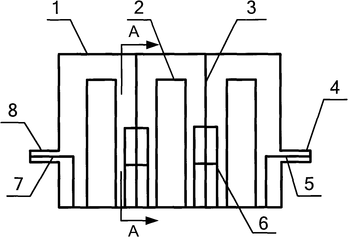
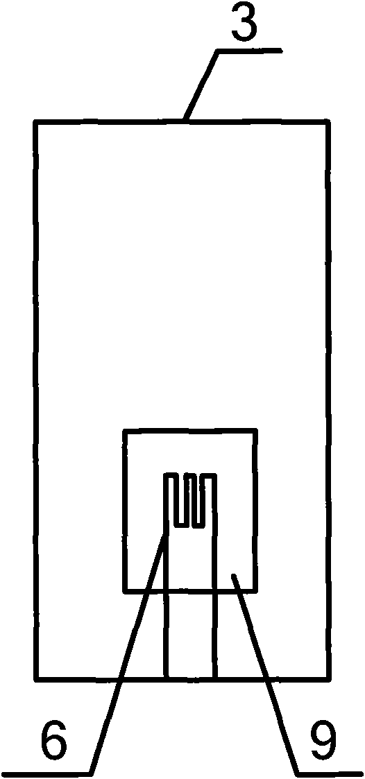
[0018] Such as figure 1 with figure 2 As shown, a coaxial cavity tunable filter with high and low end bandwidth balance, including filter housing 1, partition 3, input N-type coaxial connector 8, output N-type coaxial connector 4, input coupling ring 7 , the output coupling ring 5; the filter housing 1 is a hollow cuboid, and the input N-type coaxial connector 8 and the output N-type coaxial connector 4 are separately arranged on the two opposite side walls of the filter housing 1; two partitions 3 is arranged in parallel in the filter housing 1, and divides the filter housing 1 into three coaxial cavities; the filter housing 1 where the separator and the input N-type coaxial connector 8 and the output N-type coaxial connector 4 are located The side wall planes are parallel, and each partition 3 has a rectangular coupling window 9; the center of the bottom of each coaxial cavity is provided with a cylindrical inner conductor 2, and one end of the input coupling ring 7 is con...


PUM


Abstract

The invention relates to a coaxial cavity tunable filter with balanced bandwidth at a high end and a low end. The prior coaxial cavity tunable filter can not keep the constant bandwidth in the workingfrequency band at different frequencies. The coaxial cavity tunable filter with balanced bandwidth at the high end and the low end comprises a filter shell, wherein the filter shell is divided into aplurality of coaxial cavities by baffle plates which are provided with rectangular coupling windows; the center of the bottom in each coaxial cavity is provided with a cylindrical inner conductor; aninput coaxial joint and an output coaxial joint are respectively arranged on the two opposite side walls of the filter shell; one end of a coupling loop is connected with the coaxial joints, and theother end of the coupling loop is connected with the bottom in each cavity of the filter shell; the coupling loop among the cavities is in a solenoid type structure; and two ends of a spiral wire arerespectively positioned in two adjacent coaxial cavities, and a leading wire is led out and is connected with the bottom of the filter shell. In the invention, the filter coupling windows and the solenoid type coupling loop among the cavities are combined, and by using the structure, the bandwidth of the filter can be kept constant in the whole frequency tuning range, and the insertion loss and the ripples of the filter are greatly improved.

Description

technical field [0001] The invention belongs to the field of microwave passive circuits, and relates to a coaxial cavity tunable filter with high and low-end bandwidth balance, and more specifically relates to a coaxial cavity filter that realizes miniaturization and high and low-end bandwidth balance without reducing other performances. cavity tunable filter. Background technique [0002] The function of the filter is to pass the signal of a specific frequency and attenuate the signal outside the frequency. Generally, inter-cavity coupling can be realized by opening rectangular coupling holes between coaxial resonant cavities, thereby forming a coaxial cavity filter. The characteristic of the tunable filter is that the center frequency of the filter can be changed according to the needs, so as to realize the confidential communication. The coupling of the coaxial cavity tunable filter is usually realized through the coupling window between the cavities. [0003] It is ge...

Claims


Application Information

Patent Timeline
Patent Type & Authority Applications(China)
IPC IPC(8): H01P1/205
Inventor 官伯然张忠海王东吴恒恒
Owner HANGZHOU DIANZI UNIV
Why Eureka
Try Eureka