Semi-sliding hydraulic bulging technology of automobile axle housing part and die thereof

A hydraulic bulging and semi-sliding technology, which is applied in the manufacturing process and mold field of automobile axle housing parts, can solve the problems of small single bulging amount of tube blank, large reduction of tube wall thickness, and large equipment tonnage. , to achieve the effect of small wall thickness reduction, reasonable wall thickness distribution, and reduced quality

CN101823096BInactive Publication Date: 2013-05-08YANSHAN UNIV
0 Cites 0 Cited by

Patent Information

Authority / Receiving Office
CN · China
Patent Type
Patents(China)
Current Assignee / Owner
Publication Date
2013-05-08
Estimated Expiration
Not applicable · inactive patent

Smart Images

  • Figure 1
    Figure 1
  • Figure 2
    Figure 2
  • Figure 3
    Figure 3
Patent Text Reader

Abstract

The invention discloses a semi-sliding hydraulic bulging technology of an automobile axle housing part and a die thereof. In the invention, the semi-sliding bulging die the body of which is composed of an upper fixed module and a lower fixed module (10,10') in the middle and a left sliding module and a right sliding module (6,6') is adopted to carry out twice hydraulic bulging shaping to a reduced pipe blank (11), wherein, after hydraulic bulging shaping at the first time, the middle of the pipe blank is saddle-shaped; and after being annealed, precise shaping is achieved by secondary hydraulic bulging shaping. The upper fixed module and the lower fixed module keep motionless in the process of bulging and are used for removing the parts after bulging. The left sliding module and the rightsliding module (6,6') adopt an integral structure (or are composed of parts of axial split dies) and are respectively connected with the left sliding module and the right sliding module of a three-dimensional hydraulic machine to perform horizontal movement. The cavity of the fixed module by secondary hydraulic bulging comprises the maximum cross section of a workpiece, and the cavity of the fixed module by first hydraulic bulging is designed according to the saddle-shaped bulging pipe blank. The technology replaces a casting method and a stamping welding method, simplifies manufacturing procedures, lowers cost by 20% and improves strength and rigidity of the workpiece by 30%.
Need to check novelty before this filing date? Find Prior Art

Description

technical field

[0001] The invention relates to a manufacturing process and mold for automobile axle housing parts, in particular to a semi-sliding hydraulic bulging process and mold for automobile axle housing parts. Background technique

[0002] The axle housing of the automobile drive axle is a large-scale straight-axis pipe with complex cross-section, which requires high strength and rigidity. At present, such parts are mainly manufactured by casting method and stamping welding method. Casting parts have high strength and rigidity, and can cast different wall thicknesses, but they are heavy in quality and have many processing surfaces; stamped and welded parts are light in weight and high in productivity, but the material utilization rate is low, and it is difficult to achieve better performance with a single wall thickness Require.

[0003] Combined with the shape characteristics and performance requirements of automobile axle housing parts, it is reasonable to select...

Examples

Embodiment

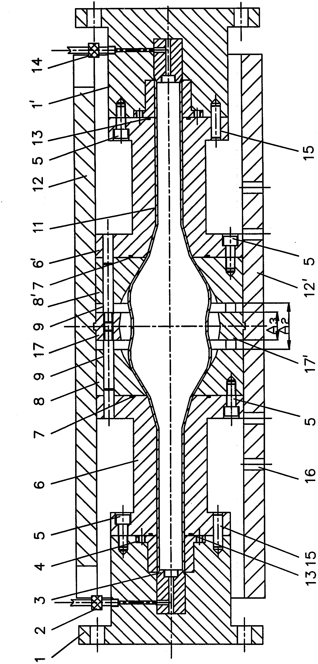
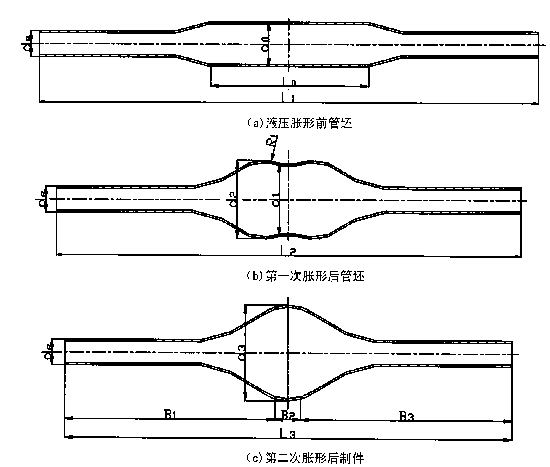
[0015] figure 1 It is a schematic diagram of the semi-sliding hydraulic bulging process for automobile axle housing parts disclosed by the present invention, image 3 , Figure 4 It is a schematic diagram of the mold structure used for the first hydraulic bulging and the second hydraulic bulging of automobile axle housing parts. In the present invention, the semi-sliding type hydraulic bulging mold of the automobile axle housing class part includes the middle upper and lower fixed modules 1 (10, 10 '), left and right sliding modules, upper mold guide plate 12, lower mold guide plate 12 ', high pressure Pipe joint 2, high pressure gauge 14 and oil discharge hole 16, wherein, the middle fixed module is divided into upper fixed module I 10 and lower fixed module I 10 ', and upper fixed module I 10 and I lower fixed module 10 ' are connected with upper die guide plate respectively 12 and lower mold guide plate 12 ' are connected together. The coaxiality is guaranteed by guide p...