Disengaging device for timepiece mechanism, and watch movement comprising this device

一种解耦装置、时计的技术,应用在解耦装置领域,能够解决占据紧邻解耦装置空间等问题

Active Publication Date: 2010-09-08
MONTRES JAQUET DROZ SAMONTRES JAQUET DROZ AGMONTRES JAQUET DROZ LTD
View PDF3 Cites 3 Cited by
  • Summary
  • Abstract
  • Description
  • Claims
  • Application Information

AI Technical Summary

Problems solved by technology

Another disadvantage is that the decoupling shaft occupies the entire headspace comprised between the base plate and the barrel bar, preventing any other element from occupying part of this headspace
Finally, the lever and its attachment to the chassis occupy the space immediately adjacent to the decoupling

Method used


Image

  • Disengaging device for timepiece mechanism, and watch movement comprising this device
  • Disengaging device for timepiece mechanism, and watch movement comprising this device
  • Disengaging device for timepiece mechanism, and watch movement comprising this device

Examples


Embodiment Construction

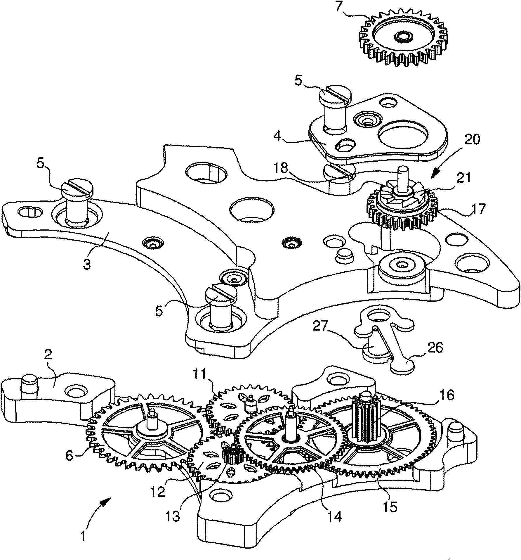
[0018] like Figure 1 to Figure 4 The illustrated self-winding mechanism 1 comprises, in a conventional manner, a rotating eccentric mass that winds the mainspring of the watch movement when it rotates under the action of the wearer's movement. Such an eccentric mass is not shown for clarity of the drawing. In this example, the position of the eccentric mass is offset from the center of the movement.

[0019] Note, especially in figure 1 In the present invention, the gear train of the mechanism 1 is made in a modular form, and its structure includes a frame 2 assembled together by screws 5 , a bridge 3 and an additional plate 4 . The entry wheel of this gear train is the setting wheel 6, which meshes with a pinion (not shown) integrally formed with the eccentric mass, and the exit element is the wheel 7, which is drivingly fixed to the engine. Ratchet 8 of small arbor 10 of barrel 9 .

[0020] When the setting wheel 6 rotates in one direction or the other, the setting whee...


PUM


Abstract

The invention concerns a vertical type uncoupling device, in particular in an automatic watch winding mechanism that includes an oscillating mass and a gear train connecting the oscillating mass to a barrel (9), wherein said gear train includes a direction reverser device (11, 12), a reduction gear (13, 14, 15, 16) and the uncoupling device (20). The uncoupling device includes two coaxial wheels (17, 7) that can be coupled in rotation in one direction owing to respective Breguet toothings (21, 22) arranged on the opposite flanks of said wheels. The coaxial wheel (17), which is mobile in the axial direction, is secured to a sliding arbour (18), which is mounted so as to rotate and slide in fixed bearings (24, 25). A return spring (26) includes an elastic strip that abuts against one end ofthe sliding arbour (18) to tend to engage and keep meshed the Breguet toothings. This design reduces friction and saves space. Other applications of this type of uncoupling device in a watch movementare described.

Description

technical field [0001] The invention relates to a decoupling device for a timepiece mechanism comprising two coaxial wheels which can be mutually connected when rotating in at least one direction by means of corresponding coupling elements arranged on opposite sides of said wheels. A coupling in which one of the coaxial wheels, called the coupling wheel, is axially movable and biased by a return spring which tends to engage the coupling elements. The invention also relates to a watch movement comprising a device of this type, in particular for use in a self-winding mechanism. Background technique [0002] In most current self-winding mechanisms, the direction reverser device is formed by a pair of unidirectionally coupled wheels arranged in parallel, for example wheels with rollers or clicks. The mainspring, resting on the train in its wound-up state, tends to rotate the train in the opposite direction as it was wound, but the reversing device locks this counter-rotation, ...

Claims


Application Information

Patent Timeline
Patent Type & Authority Applications(China)
IPC IPC(8): G04B5/14G04B19/23
CPCG04B11/008G04B5/10G04B19/23G04B19/235
Inventor R·库尔沃西尔A·布伦
Owner MONTRES JAQUET DROZ SAMONTRES JAQUET DROZ AGMONTRES JAQUET DROZ LTD
Why Eureka
Try Eureka