Reflection-type confocal scanning retina imaging system based on adaptive optics

Active Publication Date: 2012-07-11
INST OF OPTICS & ELECTRONICS - CHINESE ACAD OF SCI
View PDF5 Cites 0 Cited by
  • Summary
  • Abstract
  • Description
  • Claims
  • Application Information

AI Technical Summary

Problems solved by technology

However, this system uses a camera as an imaging detector, which can only perform single-frame exposure at a time, and cannot track changes in fundus tissue in real time; secondly, the longitudinal resolution of this system is low, close to 300 microns, and it is difficult to distinguish different layers of the retina; finally , the system uses a transmission optical path, which is not conducive to imaging in different wavelength bands
[0006] In US Patent No. US 6,890,076B2, a confocal scanning retinal imaging system based on adaptive optics is introduced. This system uses a trial lens placed at the entrance pupil of the human eye to correct system astigmatism, and does not guarantee the achromatic aberration of the main optical path. In this way, for the design band, the entire scanning field of view reaches the diffraction limit, and if the non-design band is used, the astigmatism at the edge of the field of view is large; and the system does not use another eye, which is suitable for the human eye adaptive system. It is very important to ensure the stability of the subject's eye. Experiments have shown that if the same-eye optotype is used, the subject's eye will easily turn to focus on the scanning spot instead of the target when using visible light, and the stability is difficult to guarantee.

Method used


Image

  • Reflection-type confocal scanning retina imaging system based on adaptive optics
  • Reflection-type confocal scanning retina imaging system based on adaptive optics
  • Reflection-type confocal scanning retina imaging system based on adaptive optics

Examples


Embodiment Construction

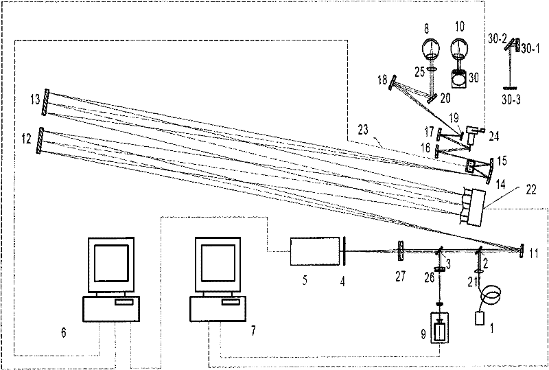
[0033] like figure 1 As shown, in the actual operation of the system, there are four processes at the same time, the main optical path transmission process, the data acquisition imaging process, the adaptive optics correction process and the subject-related process. Including a semiconductor laser light source 1, a plurality of reflective beam reduction beam expansion systems 11-18, a two-dimensional scanning galvanometer composed of an X-direction scanning galvanometer 23 and a Y-direction scanning galvanometer 24, a Hartmann wavefront sensor 9, deformation The mirror 22, the collection lens 27, the pinhole 4 and the photomultiplier tube 5, the photodetection system, the data acquisition and processing system 6, and the other eye visual target system 30. The collimating mirror 21 , the deforming mirror 22 , the X-direction scanning galvanometer 23 , the Y-direction scanning galvanometer 24 , the optometry lens 25 and the Hartmann front conjugate plane 26 are in conjugate posi...


PUM


Abstract

The invention relates to a reflection-type confocal scanning retina imaging system based on adaptive optics, which can accurately obtain the high-resolution images of vital human eye retinae in real time and comprises a light source, a reflection-type beam shrinking and expanding system, a two-dimension scanning galvanometer, a Hartmann sensor, a deformable mirror, a photoelectric detection system, a data acquisition and processing system and a contraocular sighting target system. Lasers emitted from the light source are hit into human eye ground; light reflected from the eye ground returns along the original path, enters the photoelectric detection system and passes through the data acquisition and processing system to obtain the real-time images of the human eye ground. Simultaneously, an adaptive optics system comprising the Hartmann sensor and the deformable mirror can synchronously detect and correct human eye aberration, and thereby, the high resolution of the images is ensured.

Description

technical field [0001] The invention relates to a medical imaging diagnosis system for high-resolution imaging of the retina, in particular to a total reflection confocal scanning retinal imaging system based on adaptive optics and another eye target. Background technique [0002] The retinal image of the human eye is an indispensable and important information in ophthalmic diagnosis and treatment. Medical research and clinical studies have proved that diseases such as diabetes, arteriovenous thrombosis, hypertension, anemia, nephropathy, pregnancy-induced hypertension syndrome and tumors can all be reflected in the fundus microcirculation, and abnormal fundus metabolism leads to fundus lesions. Real-time tracking of the topographic changes of the fundus and retina will help in the early diagnosis and prevention of the above-mentioned physical diseases. In 1987, R.H.Webb applied the confocal scanning technology to the retinal imaging of the living human eye. However, the li...

Claims


Application Information

Patent Timeline
Patent Type & Authority Patents(China)
IPC IPC(8): A61B3/12A61B3/15
Inventor 张雨东卢婧李昊史国华饶学军
Owner INST OF OPTICS & ELECTRONICS - CHINESE ACAD OF SCI
Why Eureka
Try Eureka