Mine cement foaming machine

A cement foaming and cement technology, applied in ceramic molding machines, manufacturing tools, etc., can solve the problems of affecting the stability and strength of foam, difficult to control, uneven size of foam, etc., and achieve fast gas-liquid mixing speed, easy manufacturing or The effect of renovation and improvement of construction efficiency

Inactive Publication Date: 2010-12-22
HENAN FUCHENG ECOLOGICAL ENERGY TECH
View PDF5 Cites 5 Cited by
  • Summary
  • Abstract
  • Description
  • Claims
  • Application Information

AI Technical Summary

Problems solved by technology

[0002]At present, the windbreak wall or firewall built in the mine is constructed by ordinary masonry, which is time-consuming and laborious, and the efficiency is low
The walls built with cloth and sand have the defects of poor sealing and poor firmness
Cement pouring walls can meet the above deficiencies, but the current cement foaming machines are not suitable for underground operations
Moreover, there is still a certain gap in the foaming performance of the existing foaming machines, which needs to be further improved. For example, the existing problem is that the bubbles are rarely generated.
The more important thing is that the size of the foam is uneven, which affects the stability and strength of the foam, and the amount of foam produced is very random and difficult to control

Method used


Image

  • Mine cement foaming machine
  • Mine cement foaming machine
  • Mine cement foaming machine

Examples


Embodiment 1

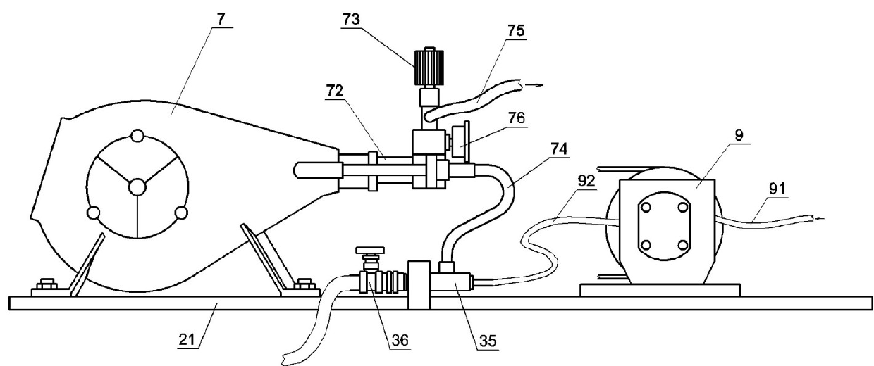
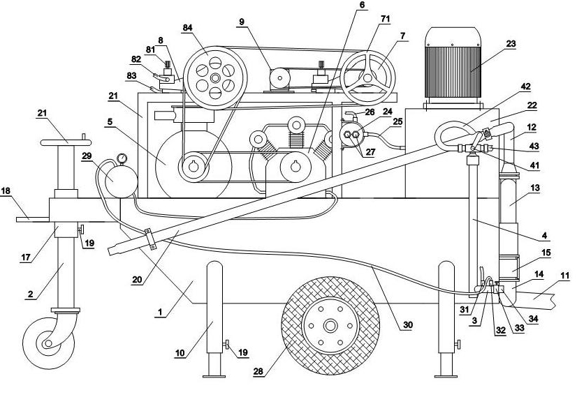
[0025] Embodiment one: see figure 1 , figure 2 , image 3 , Figure 4 , the number 1 in the figure is the frame, 2 is the front side walking wheel, 3 is the horizontal pipe of the foam maker, 4 is the vertical pipe of the foam maker, 5 is the explosion-proof motor, 6 is the hydraulic conveying mechanism, and 7 is the foaming Piston pump, 8 is a quick-setting plunger pump, 9 is a micro pump, 10 is a telescopic outrigger, 11 is a main pipe for suction of cement slurry, 12 is a main pipe for output of cement slurry, 13 is a branch pipe for output of cement slurry, and 14 is for cement slurry Suction pipe, 15 is the support, 16 is the air compressor, 17 is the fixed sleeve, 18 is the pulling arm, 19 is the fastening bolt, 20 is the foam delivery pipe of the cement slurry delivery mechanism, 21 is the rotating wheel, 22 is the oil tank , 23 is a hydraulic pump, 24 is a cooler, 25 is an oil outlet pipe of a fuel tank, 26 is an oil outlet pipe of a cooler, 27 is a cold water inle...

Embodiment 2

[0031] Embodiment 2: The accompanying drawings are not drawn, and the content is basically the same as that of Embodiment 1, and the similarities will not be repeated. The difference is that a plurality of pulleys with different diameters are installed on the rotating shaft of the micropump at the same time, and different pulleys are driven to achieve alignment. Foaming agent should be controlled as much as possible or output.


PUM


Abstract

The invention relates to a mine cement foaming machine which comprises a stand, a cement slurry conveying mechanism and a hydraulic system, wherein an explosion-proof motor is installed on the stand and is used for simultaneously driving a foaming plunger pump and a micropump; an output pipe of the foaming plunger pump is communicated with a foam producing device; an output shaft of the explosion-proof motor is used for also driving an air compressor; an output air pipe of the air compressor is communicated with the foam producing device; and the foam producing device passes through a pipeline and is communicated with the output pipe of the cement slurry conveying mechanism after a valve is installed. The invention can be suitable for mine operation and is capable of rapidly constructing walls in an underground tunnel, such as a windbreak wall, and the like and has time saving, labor saving and high working efficiency. The whole machine adopts a manual control valve or a mechanical control valve, meets the mine working condition, has the advantages of safety, reliability, convenient use and easy manufacture or reformation, is suitable for mass production and is quite beneficial to popularization and construction.

Description

Technical field: [0001] The invention relates to a cement foaming machine used in the field of mining safety, in particular to a cement foaming machine for underground use. Background technique: [0002] At present, the windbreak walls or firewalls built in mines are built in ordinary masonry methods, which is time-consuming and labor-intensive, and the efficiency is low. The body of wall that is piled up with sand by cloth tape has the defects of poor sealing and poor firmness. Cement pouring walls can meet the above deficiencies, but the current cement foaming machines are not suitable for underground operations. Moreover, there is still a certain gap in the foaming performance of the existing foaming machine, which needs to be further improved. For example, the existing problem is that the bubbles are rarely generated. More importantly, the size of the foam is uneven, which affects the stability and strength of the foam, and the amount of foam produced is very random an...

Claims


Application Information

Patent Timeline
Patent Type & Authority Applications(China)
IPC IPC(8): B28B1/50
Inventor 于水军何贵新何贵忠王永胜申安州
Owner HENAN FUCHENG ECOLOGICAL ENERGY TECH
Why Eureka
Try Eureka