Video synchronization pixel clock generating circuit

A pixel clock and circuit generation technology, applied in television, electrical components, image communication, etc., can solve the problems of unstable and effective image display, line length jitter, video data jitter, etc.

Active Publication Date: 2012-08-08
CHENGDU CORPRO TECH CO LTD
View PDF0 Cites 0 Cited by
  • Summary
  • Abstract
  • Description
  • Claims
  • Application Information

AI Technical Summary

Problems solved by technology

However, the video signal usually sent to the decoder, whether it is generated by a camera, DVD or other types of video signal sources, even if the signal is relatively stable, there is a certain deviation from the ideal standard signal, that is, the line length jitters within a certain range
In addition, for non-standard video signals outside the specifications, such as analog video signals recorded on video tapes, etc., due to the long-term deterioration of the tape or the difference between the recording device and the playback device, it cannot be reproduced under the same conditions as when recorded. , the total line number and line length of each frame may change drastically, especially during the field blanking period, and the change range may even be as high as ±10%, which usually causes horizontal or vertical jitter in the decoded video data, making the image Unable to display stably and effectively

Method used


Image

  • Video synchronization pixel clock generating circuit
  • Video synchronization pixel clock generating circuit
  • Video synchronization pixel clock generating circuit

Examples


Embodiment Construction

[0019] Explanation of technical terms in the text:

[0020] DDS is a direct digital frequency synthesizer (Direct Digital Synthesizer).

[0021] The present invention will be further described below in conjunction with the accompanying drawings and embodiments.

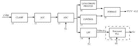
[0022] Such as figure 2 Shown is a block diagram of a video decoding circuit combined with the present invention. The video signal CVBS signal (or S-Video signal) is first clamped by the CLAMP module 11 to restore the DC level of the video signal, and then through the AGC module 12, a video signal that meets the quantization range of the ADC is constructed, and then the analog video signal is converted by the ADC module 13. The signal is quantized into a digital video signal, and then the video data is subjected to bright color processing through the LUM / CHROM PROCESS module 16 to separate the brightness information Y and the chrominance information C, and the brightness information Y is further peaked to generate ...


PUM


Abstract

The invention provides a video synchronization pixel clock generating circuit. The circuit performs low-pass filtering on an ADC-quantized CVBS or S-video signal, filters high-frequency information of over 1MHz to obtain line blanking edge information of the video signal, performs phase discrimination, performs error detection and error filtering to obtain an error value, obtains output of a 6-bit lookup table and finally performs double frequency multiplication or quadruple frequency multiplication on the signal through PLL so as to generate the pixel clock of 13.5MHz and a working clock of 27MHz of a chip.

Description

technical field [0001] The present invention relates to a synchronous pixel clock generation circuit for video, in particular to a technique for internally generating an adapted pixel clock based on an externally input video signal. The present invention can be used for non-standard video sources such as standard video sources and VCR. Standard video source. Background technique [0002] In the video signal, there are NTSC, PAL and other formats, 50Hz or 60Hz and other field frequencies, ideal standard video signals of different specifications, such as figure 1 As shown, it is mainly composed of "front porch", "sync head", "back porch", "rising / falling edge" and effective video signal during the line blanking period, and the line sync head represents the start of each line of video signal The position also represents that the decoded video data is at the leftmost end of each row of the monitor. Generally, the circuit can simply control the phase-locked loop PLL to regenerat...

Claims


Application Information

Patent Timeline
Patent Type & Authority Patents(China)
IPC IPC(8): H04N7/01H04N5/04H04N5/14H04N7/26
Inventor 向多春陈庆华
Owner CHENGDU CORPRO TECH CO LTD
Why Eureka
Try Eureka