Solar device and manufacturing method thereof

A solar energy device and solar energy technology, applied in photovoltaic power generation, electrical components, circuits, etc., can solve the problems of low heat dissipation efficiency of solar cell structure, unsatisfactory metal heat dissipation effect, and high cost of heat dissipation device, and achieve good heat dissipation effect and low cost. , the effect of good thermal conductivity

Inactive Publication Date: 2011-02-02
HONG FU JIN PRECISION IND (SHENZHEN) CO LTD +1
View PDF3 Cites 2 Cited by
  • Summary
  • Abstract
  • Description
  • Claims
  • Application Information

AI Technical Summary

Problems solved by technology

[0005] However, the cost of heat sinks made of metal is relatively high, and the heat dissipation effect of metal is not ideal, which makes the heat dissipation efficiency of the solar cell structure low and the cost is high

Method used


Image

  • Solar device and manufacturing method thereof
  • Solar device and manufacturing method thereof
  • Solar device and manufacturing method thereof

Examples


Embodiment Construction

[0012] The present invention will be described in further detail below in conjunction with the accompanying drawings.

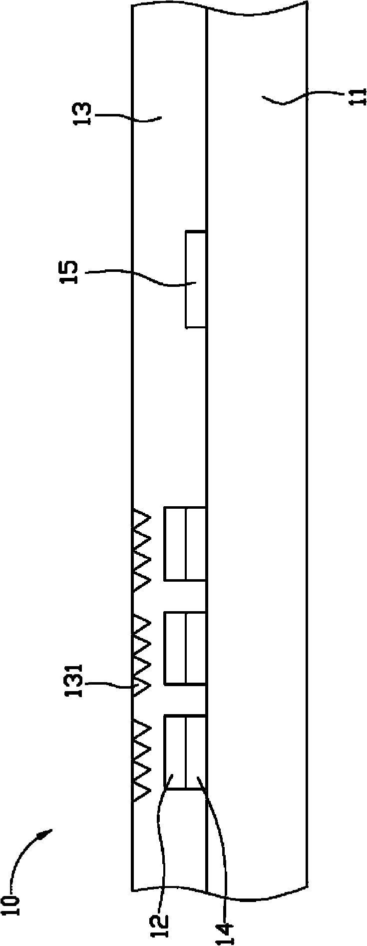
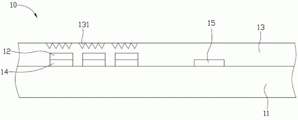
[0013] see figure 1 As shown, the solar device 10 according to the first embodiment of the present invention includes a ceramic substrate 11 , several III-V solar chips 12 , a packaging body 13 , an adhesive layer 14 and a circuit unit 15 .

[0014] The area of ​​each III-V group solar chip 12 is greater than or equal to 1 square millimeter (mm 2 ) and less than or equal to 9 square millimeters, which are electrically connected to the circuit unit 15 and arranged on the ceramic substrate 11 in an appropriate manner to receive sunlight and convert sunlight into electrical energy output, for example, the III-V solar chip 12 utilizes an adhesive layer 14 is fixed on the ceramic substrate 11.

[0015] Preferably, an array of III-V group solar chips 12 is disposed on a ceramic substrate 11 .

[0016] The III-V solar chip 12 may be a gallium nitride (GaN) solar ...


PUM


Abstract

The invention relates to a solar device which comprises a ceramic base plate, a plurality of III-V group solar chips, and an encapsulation body, wherein the III-V group solar chips are arranged on the ceramic base plate and are used for converting solar energy into electric energy on the ceramic base plate; and the encapsulation body covers the ceramic base plate and the III-V group solar chips, at least one Fresnel lens is formed on the position of the encapsulation body corresponding to the III-V group solar chips, and sunlight passes through the Fresnel lens and is converged on the III-V group solar chips.

Description

technical field [0001] The invention relates to a solar device and a manufacturing method thereof. Background technique [0002] With the rapid development of industry, the gradual depletion of fossil fuels and the emission of greenhouse gases have attracted worldwide attention, and the stable supply of energy has become a major global issue. [0003] Compared with traditional coal-fired, gas-fired or nuclear power generation, solar cells (solar cells) use the photoelectricity effect to directly convert solar energy into electrical energy, so there is no accompanying production of greenhouse effect gases such as carbon dioxide, nitrogen oxides, and sulfur oxides. polluting gases, and can reduce dependence on fossil fuels and provide a safe and autonomous source of electricity. [0004] The general solar cell structure is to integrate the solar chip, driving circuit, etc. on a substrate, and then weld a metal substrate on the substrate as a heat sink to guide the heat genera...

Claims


Application Information

Patent Timeline
Patent Type & Authority Applications(China)
IPC IPC(8): H01L31/052H01L31/048H01L31/18
CPCY02E10/52H01L31/0522H01L31/052H01L31/048H01L31/0543
Inventor 余泰成黄雍伦
Owner HONG FU JIN PRECISION IND (SHENZHEN) CO LTD
Why Eureka
Try Eureka