Magnetic valve

A technology of solenoid valve and valve seat, applied in the field of solenoid valve

Active Publication Date: 2013-07-03
ZHEJIANG SANHUA INTELLIGENT CONTROLS CO LTD
View PDF10 Cites 2 Cited by
  • Summary
  • Abstract
  • Description
  • Claims
  • Application Information

AI Technical Summary

Problems solved by technology

[0012] In addition, the existing technology adopts flat sealing, and the actual pressure on the sealing plug is greater than the product of the valve port area and the pressure difference.

Method used


Image

  • Magnetic valve
  • Magnetic valve
  • Magnetic valve

Examples


Embodiment approach

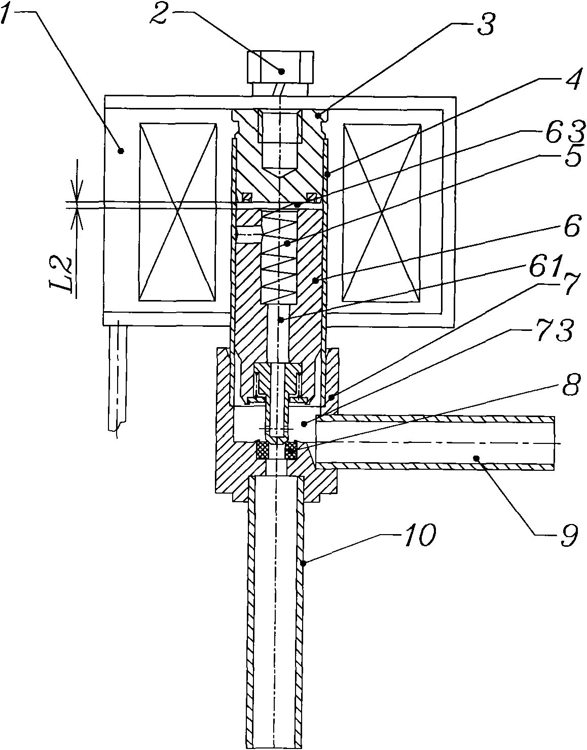
[0041] Introduce the second embodiment of the present invention below, image 3 It is a structural schematic diagram of the second embodiment of the solenoid valve of the present invention, Figure 4 for image 3 The schematic diagram of the partially enlarged structure of the valve port between the seal and the valve seat when the solenoid valve shown is closed, Figure 5 for image 3 The partial enlarged structural diagram of the seal and the valve port of the solenoid valve shown at the moment of opening, Image 6 for image 3 The partial enlarged structure diagram of the seal and the valve port after the solenoid valve is opened is shown.

[0042] As shown in the figure, the main difference between this embodiment and the above-mentioned first embodiment is that the valve seat in this embodiment is formed by a combined structure: the valve seat includes a valve seat portion 7 and a valve port portion 8, which are formed by combination, The valve port 8 is made of engi...


PUM


Abstract

The invention relates to a magnetic valve, comprising a valve seat, a sleeve fixedly connected with the valve seat, a coil arranged outside of the sleeve, a movable core arranged in the sleeve, a static core and a reset spring arranged between the movable core and the static core, wherein a sealing element is arranged at one end of the movable core opposite to the other end close to the static core, and a valve port is arranged at the side opposite to the sealing element in a valve body; and the sealing element comprises a major diameter part in the central cavity body at the end part of the movable core, a middle part and a minor diameter part which partially extends out of the central cavity body at the end part of the movable core. The magnetic valve also is provided with a balance channel passing through the sealing element, so that no pressure difference generates at the two sides of the sealing element, thus avoiding instable magnetic valve flow due to action of the sealing element resulted from the pressure difference, and solving the problem of larger stress of the sealing element, thereby reducing abrasion of the sealing element.

Description

technical field [0001] The invention relates to the field of control valves, in particular to a solenoid valve used in HVAC, refrigeration and other control systems, such as a solenoid valve used in ice machines and air conditioners. Background technique [0002] Solenoid valves are often used in HVAC, refrigeration and other systems involving temperature control and regulation to control the on-off of the medium in the piping system. [0003] Please refer to Figure 7 , Figure 8 , Figure 7 It is a structural schematic diagram of a typical solenoid valve in the prior art, Figure 8 for Figure 7 The partially enlarged schematic diagram of the sealing plug and valve port of the solenoid valve shown. [0004] The solenoid valve in the prior art includes an inlet pipe 30 , an outlet pipe 31 and a valve seat 21 respectively communicating with the two, and the valve seat 21 has a valve port 211 . A sealing plug 22 is arranged in the medium channel of the electromagnetic valv...

Claims


Application Information

Patent Timeline
Patent Type & Authority Patents(China)
IPC IPC(8): F16K1/00F16K1/32F16K31/06F16K47/04
Inventor 严卫林
Owner ZHEJIANG SANHUA INTELLIGENT CONTROLS CO LTD
Why Eureka
Try Eureka