
Reactive power control method and device for a four-quadrant current source converter

A technology of current source converter and power control, applied in reactive power adjustment/elimination/compensation, reactive power compensation, etc., can solve the problems of large switching loss and large stress of switching devices, and achieve the effect of reducing dynamic switching loss

Active Publication Date: 2019-06-04
GLOBAL ENERGY INTERCONNECTION RES INST CO LTD +2
View PDF1 Cites 0 Cited by
  • Summary
  • Abstract
  • Description
  • Claims
  • Application Information

AI Technical Summary

Problems solved by technology

[0006] The present invention provides a reactive power control method and device for a four-quadrant current source converter to at least solve the large switching loss and current The problem of high stress on switching devices caused by the rapid cutting-off of the current of the source converter at high frequency

Method used


Image

  • Reactive power control method and device for a four-quadrant current source converter
  • Reactive power control method and device for a four-quadrant current source converter
  • Reactive power control method and device for a four-quadrant current source converter

Examples


Embodiment 1

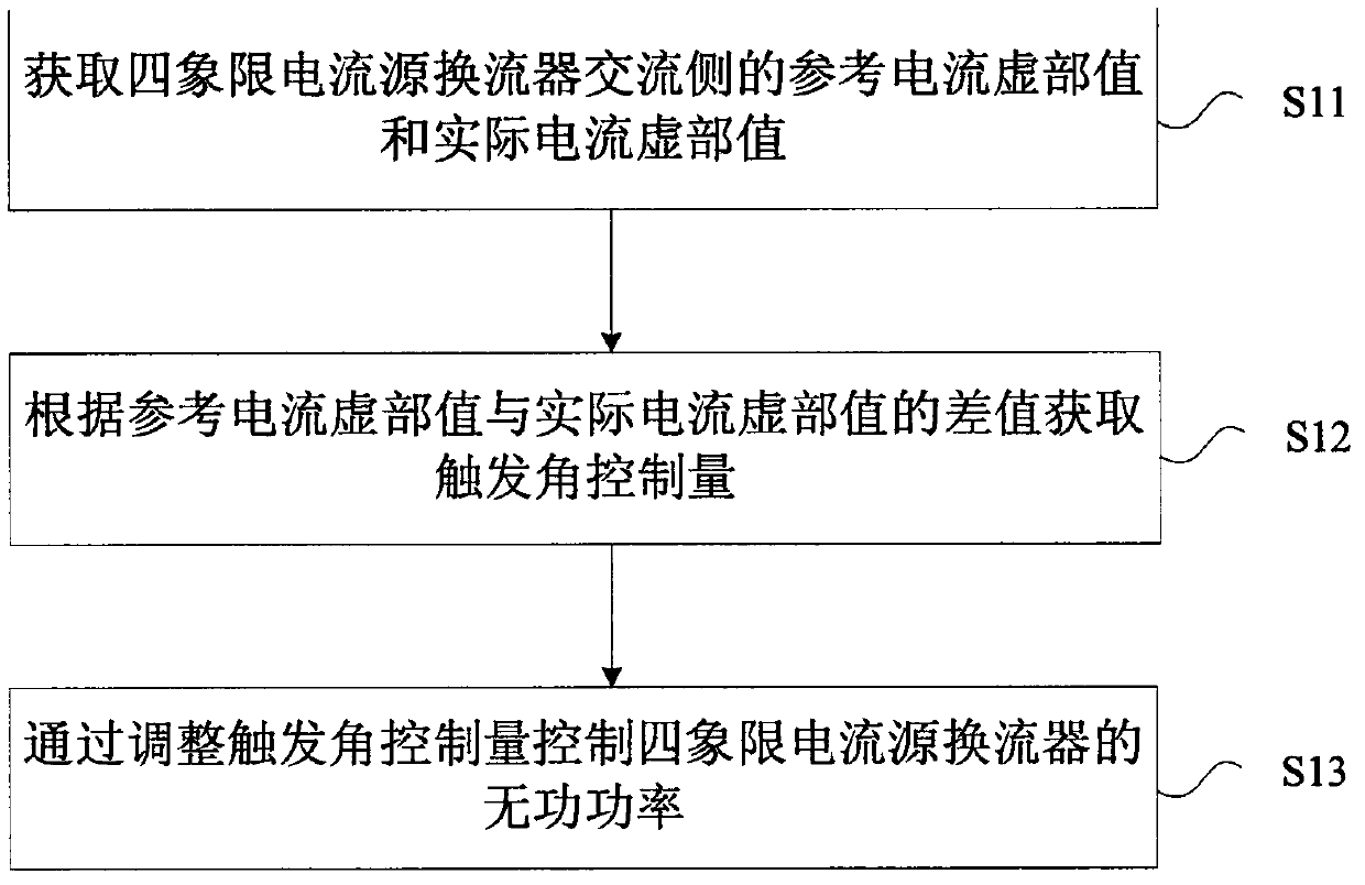
[0046] In this embodiment, a reactive power control method of a four-quadrant current source converter is provided, figure 1 is a flowchart of a reactive power control method for a four-quadrant current source converter according to an embodiment of the present invention, as figure 1 As shown, the process includes the following steps:

[0047] Step S11, obtaining the reference current imaginary part value and the actual current imaginary part value of the AC side of the four-quadrant current source converter;

[0048] Step S12, obtain the firing angle control amount according to the difference between the imaginary part value of the reference current and the imaginary part value of the actual current; preferably, input the difference value to the proportional-integral-derivative controller, through which Output the firing angle control amount;

[0049] Step S13, controlling the reactive power of the four-quadrant current source converter by adjusting the firing angle control...


PUM


Abstract

The invention provides a reactive power control method and device of a four-quadrant current source converter. The reactive power control method comprises the steps of obtaining a reference current imaginary part value and an actual current imaginary part value at an AC (Alternating Current) side of the four-quadrant current source converter; obtaining a triggering angle control quantity based on the difference value between the reference current imaginary part value and the actual current imaginary part value; and controlling the reactive power of the four-quadrant current source converter by adjusting the triggering angle control quantity. The reactive power control method and device of the four-quadrant current source converter solve the problems in the prior art that relatively big switching loss is resulted when a PWM control technology is adopted for reactive power control of the current source converter and relatively great stress may be generated for a switch device by the current source type converter when the current is cut off at a high frequency.

Description

technical field [0001] The invention relates to the technical field of control of current source converters, in particular to a method and device for controlling reactive power of a four-quadrant current source converter. Background technique [0002] The traditional current source type converter is composed of two three-phase full-bridge converters connected in parallel or in series through a Δ-Y, Y-Y-connected isolation transformer, but the AC side current will contain a lot of harmonics, and a large amount of harmonics are required when connecting to the power system. The snubber capacitor increases the cost and floor area of ​​the converter. The current source converter using the thyristor as the main bridge converter valve can only be turned on by the trigger signal, but cannot be turned off. Therefore, the phase shift range of the trigger angle of the three-phase bridge is 0° to 180°, which does not have The reactive power control capability needs to be equipped with ...

Claims


Application Information

Patent Timeline
Patent Type & Authority Patents(China)
IPC IPC(8): H02J3/18
CPCY02E40/30
Inventor 祁欢欢于弘洋蔡林海王永何金城尹晓旭赵国亮
Owner GLOBAL ENERGY INTERCONNECTION RES INST CO LTD
Learn More