Heteropolar Permanent Magnet Bias Hybrid Radial Magnetic Bearings

A permanent magnet bias and hybrid radial technology, applied in the field of magnetic bearings, can solve the problems of large electric excitation loss, magnetomotive force, leakage of permanent magnets, and large radial size, so as to improve space utilization and dynamic loss. Low, the effect of reducing the outer diameter of the stator

Active Publication Date: 2018-10-16
NAVAL UNIV OF ENG PLA
View PDF12 Cites 0 Cited by
  • Summary
  • Abstract
  • Description
  • Claims
  • Application Information

AI Technical Summary

Problems solved by technology

In this way, if the auxiliary air gap is too large, the electric excitation will lose a large magnetomotive force at the auxiliary air gap, and if the auxiliary air gap is small, the magnetic flux leakage of the permanent magnet will be serious
[0007] The permanent magnet and electric excitation magnetic fields of almost all existing heteropolar permanent magnet bias hybrid radial magnetic bearings are superimposed at the position of the yoke, resulting in a thicker yoke and a larger radial dimension

Method used


Image

  • Heteropolar Permanent Magnet Bias Hybrid Radial Magnetic Bearings
  • Heteropolar Permanent Magnet Bias Hybrid Radial Magnetic Bearings
  • Heteropolar Permanent Magnet Bias Hybrid Radial Magnetic Bearings

Examples


Embodiment Construction

[0028] The present invention will be further described in detail below in conjunction with the accompanying drawings and specific embodiments.

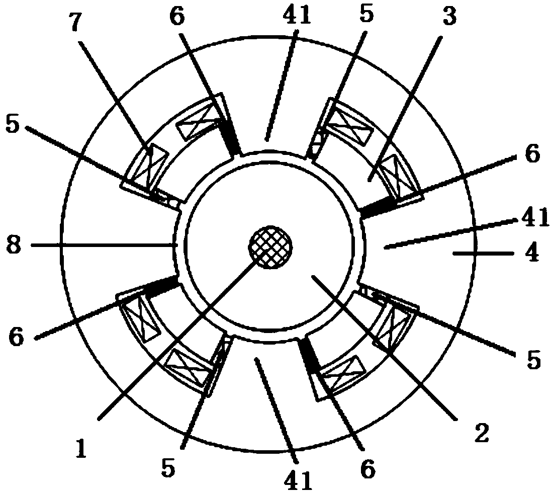
[0029] see figure 1 , The heteropolar permanent magnet bias hybrid radial magnetic bearing provided by the preferred embodiment of the present invention includes a stator assembly and a rotor assembly magnetically suspended in the stator assembly.

[0030] The rotor assembly includes a rotating shaft 1 and a rotor core 2 arranged outside the rotating shaft 1 . The rotor core 2 is shrink-fitted on the rotating shaft 1, and the size of the rotating shaft 1 depends on the design of the entire rotor system. The inner and outer surfaces of each component of the rotor assembly (rotating shaft 1, rotor core 2) are smooth curved surfaces. From the perspective of reducing size and improving space utilization, the rotating shaft 1 is preferably made of high-strength alloy steel. In this embodiment, the rotating shaft 1 is made of 25Cr2Ni4MoV,...


PUM


Abstract

The invention discloses a heterospolar type permanent magnet bias mixed radial magnetic bearing. The heterospolar type permanent magnet bias mixed radial magnetic bearing comprises a stator assembly and a rotor assembly. The rotor assembly comprises a rotary shaft and a rotor iron core arranged outside the rotary shaft. The stator assembly comprises auxiliary magnetic poles, a stator iron core, permanent magnets and excitation coils. Stator magnetic poles with the number of the multiple of four are distributed on the inner surface of the stator iron core evenly at intervals in the circumferential direction. One auxiliary magnetic pole is arranged between every two adjacent stator magnetic poles. One permanent magnet is embedded between each stator magnetic pole and the adjacent auxiliary magnetic pole. The magnetizing directions of every two adjacent permanent magnets are opposite. One set of excitation coils are arranged in a groove between every two adjacent stator magnetic poles. Work air gaps are arranged between the surfaces, toward the axes, of the stator magnetic poles and the auxiliary magnetic poles, and the outer surface of the rotor iron core. An electrical excitation magnetic path of the magnetic bearing does not pass the permanent magnets, additional air gaps do not exist, the auxiliary magnetic poles effectively solve the problem that the stator yoke thickness is large, the stator outer diameter can be reduced, and the space utilization ratio is increased.

Description

technical field [0001] The invention belongs to the field of magnetic bearings, in particular to a heteropolar permanent magnet bias hybrid radial magnetic bearing. Background technique [0002] There are two types of permanent magnetic bias hybrid radial magnetic bearings: homopolar permanent magnetic bias hybrid radial magnetic bearings (hereinafter referred to as homopolar magnetic bearings) and heteropolar permanent magnetic bias hybrid radial magnetic bearings. The difference between the two is the relationship between the permanent magnet bias magnetic field and the electric excitation control magnetic field. If the permanent magnet bias magnetic field and the electric excitation control magnetic field are not in the same plane, this type of magnetic bearing is a homopolar magnetic bearing; if the two magnetic fields are in the On the same plane, this type of magnetic bearing is a heteropolar permanent magnetic bias hybrid radial magnetic bearing. [0003] Due to the ...

Claims


Application Information

Patent Timeline
Patent Type & Authority Patents(China)
IPC IPC(8): F16C32/04
CPCF16C32/0459
Inventor 王东吴磊涛张贤彪苏振中庄虔鑫刘海涛孟繁庆
Owner NAVAL UNIV OF ENG PLA
Why Eureka
Try Eureka