A Permanent Magnetic Bias Hybrid Axial Magnetic Bearing

A technology of axial magnetic bearing and permanent magnet bias, which is applied in the field of magnetic levitation, can solve the problems of increased installation process, difficulty, and difficult installation of coils, and achieves reduced electric excitation current, small electric excitation magnetomotive force, and high electric excitation efficiency Effect

Active Publication Date: 2016-03-30
NAVAL UNIV OF ENG PLA
View PDF6 Cites 0 Cited by
  • Summary
  • Abstract
  • Description
  • Claims
  • Application Information

AI Technical Summary

Problems solved by technology

[0003] There are some deficiencies in the structure of hybrid axial bearings at present: some adopt rotor single thrust plate structure, the coil is placed in the stator slot, and the permanent magnet is placed on the thrust plate of the rotor. Although the magnetic circuit model is simplified, the installation process is increased. difficult, and the brittle nature of the permanent magnet limits the application of this structure in high-speed applications; Difficult to install, not suitable for high-speed occasions; some structures place permanent magnets and coils in the stator core at the same time, which is easy to install, but the electric excitation magnetic circuit passes through the permanent magnets, causing the electric excitation magnetic field to repeatedly demagnetize the permanent magnets during operation. Shorten the life of the permanent magnets and reduce the reliability of the system

Method used


Image

  • A Permanent Magnetic Bias Hybrid Axial Magnetic Bearing
  • A Permanent Magnetic Bias Hybrid Axial Magnetic Bearing
  • A Permanent Magnetic Bias Hybrid Axial Magnetic Bearing

Examples


Embodiment Construction

[0023] In order to make the object, technical solution and advantages of the present invention clearer, the present invention will be further described in detail below in conjunction with the accompanying drawings and embodiments. The specific embodiments described here are only used to explain the present invention, not to limit the present invention. In addition, the technical features involved in the various embodiments of the present invention described below can be combined with each other as long as they do not constitute a conflict with each other.

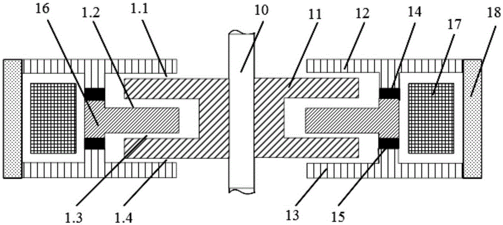
[0024] Such as figure 1 A permanent magnet bias hybrid axial magnetic bearing is shown, including a rotor assembly and a stator assembly. The rotor assembly includes a rotating shaft 10 and a rotor double thrust disk 11 set on the rotating shaft 10; the outer diameters of the two thrust disks of the rotor double thrust disk 11 are equal, which is an axisymmetric structure; due to the influence of the rotating speed, the ro...


PUM


Abstract

The invention discloses a permanent magnet polarization hybrid axial magnetic bearing. The permanent magnet polarization hybrid axial magnetic bearing comprises a rotor assembly and a stator assembly, wherein the rotor assembly comprises a rotating shaft and a rotor dual-thrust disc; the stator assembly comprises a stator shell, an upper stator end plate, an upper permanent magnet, a stator center plate, a lower permanent magnet, a lower stator end plate and a stator magnet exciting coil; the upper stator end plate and the lower stator end plate can form an outer upper air gap and an outer lower air gap together with the outer end surface of the rotor dual-thrust disc respectively, and the stator center plate and the inner end surface of the rotor dual-thrust disc can form an inner upper air gap and an inner lower air gap; the upper permanent magnet and the lower permanent magnet can axially magnetized, and magnetizing directions of the upper permanent magnet and the lower permanent magnet are opposite; the inner and outer air gaps can internally generate a permanent magnet polarization magnetic field, a magnetic field generated by the stator magnet exciting coil can regulate the permanent magnet polarization magnetic field. The magnetic bearing provided by the invention has a firm and reliable structure and high energy density, can be applied in a high-speed operation occasion, and is suitable for a high-speed system which has high power and large capacity.

Description

technical field [0001] The invention belongs to the technical field of magnetic levitation, and more specifically relates to a permanent magnet bias hybrid axial magnetic bearing with low standby loss; it can be applied to low-loss high-speed occasions such as flywheel energy storage systems, electric spindles, and satellite reaction wheels. Background technique [0002] Axial magnetic bearing is a high-performance new bearing that uses the magnetic force between the stator and rotor to keep them from contacting each other, so as to control the axial movement of the rotor with a single degree of freedom. Axial magnetic bearings can be divided into three categories according to the way the magnetic force is provided: pure Permanent magnet axial bearings, pure electric excitation axial bearings and permanent magnet bias hybrid axial bearings. Among them, the pure permanent magnet axial bearing has low loss and simple structure, but the stiffness is small, and the state of the ...

Claims


Application Information

Patent Timeline
Patent Type & Authority Patents(China)
IPC IPC(8): F16C32/04
Inventor 王东苏振中吴磊涛张贤彪王抗易新强林楠
Owner NAVAL UNIV OF ENG PLA
Why Eureka
Try Eureka