Hoisting process for rotating wheel of vertical shaft axial flow hydraulic turbine

An axial-flow, water-turbine technology, applied in the direction of hoisting device, hoisting device, etc., can solve problems such as troublesome use and poor working conditions

Inactive Publication Date: 2011-05-18
浙江富春江水电设备股份有限公司
View PDF4 Cites 8 Cited by
  • Summary
  • Abstract
  • Description
  • Claims
  • Application Information

AI Technical Summary

Problems solved by technology

However, with years of inspection of the sports unit, it is generally reported that it is very troublesome to use, and the working conditions in the machine pi...

Method used


Image

  • Hoisting process for rotating wheel of vertical shaft axial flow hydraulic turbine
  • Hoisting process for rotating wheel of vertical shaft axial flow hydraulic turbine

Examples


Embodiment Construction

[0009] Further explain below in conjunction with accompanying drawing:

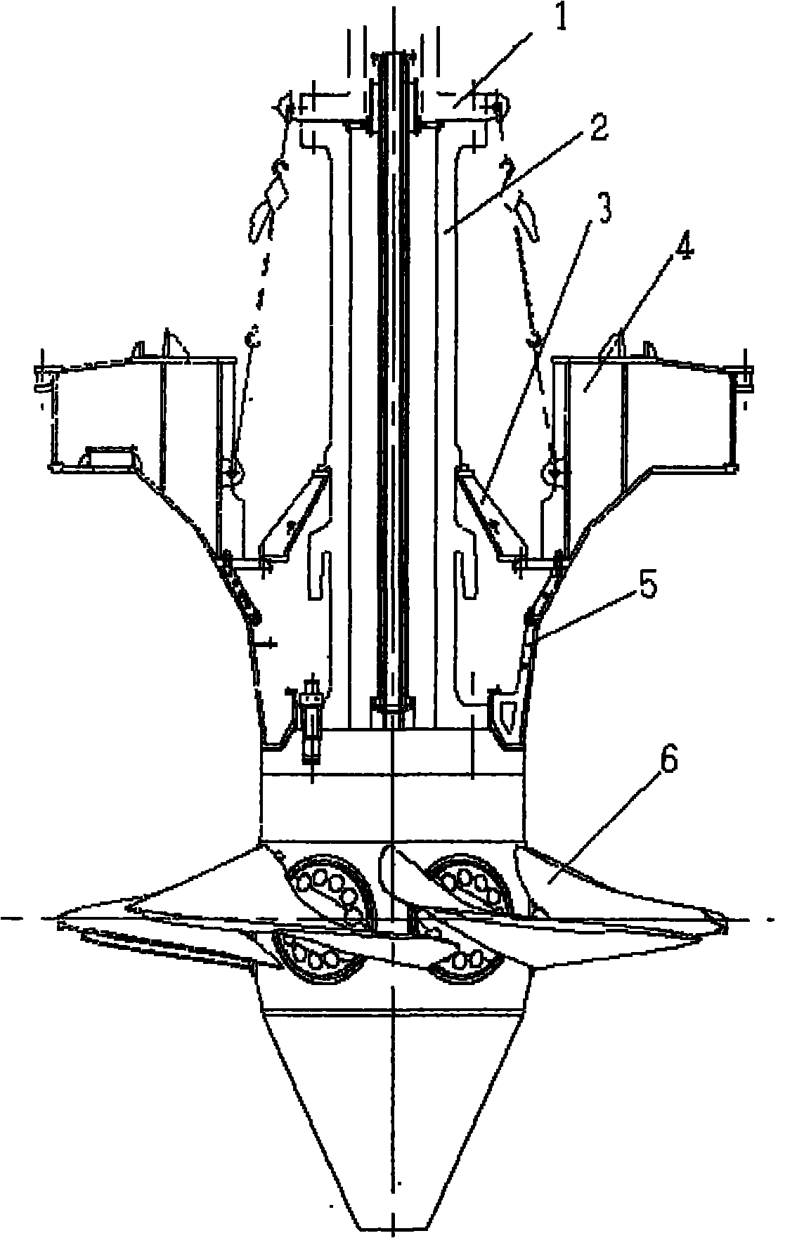
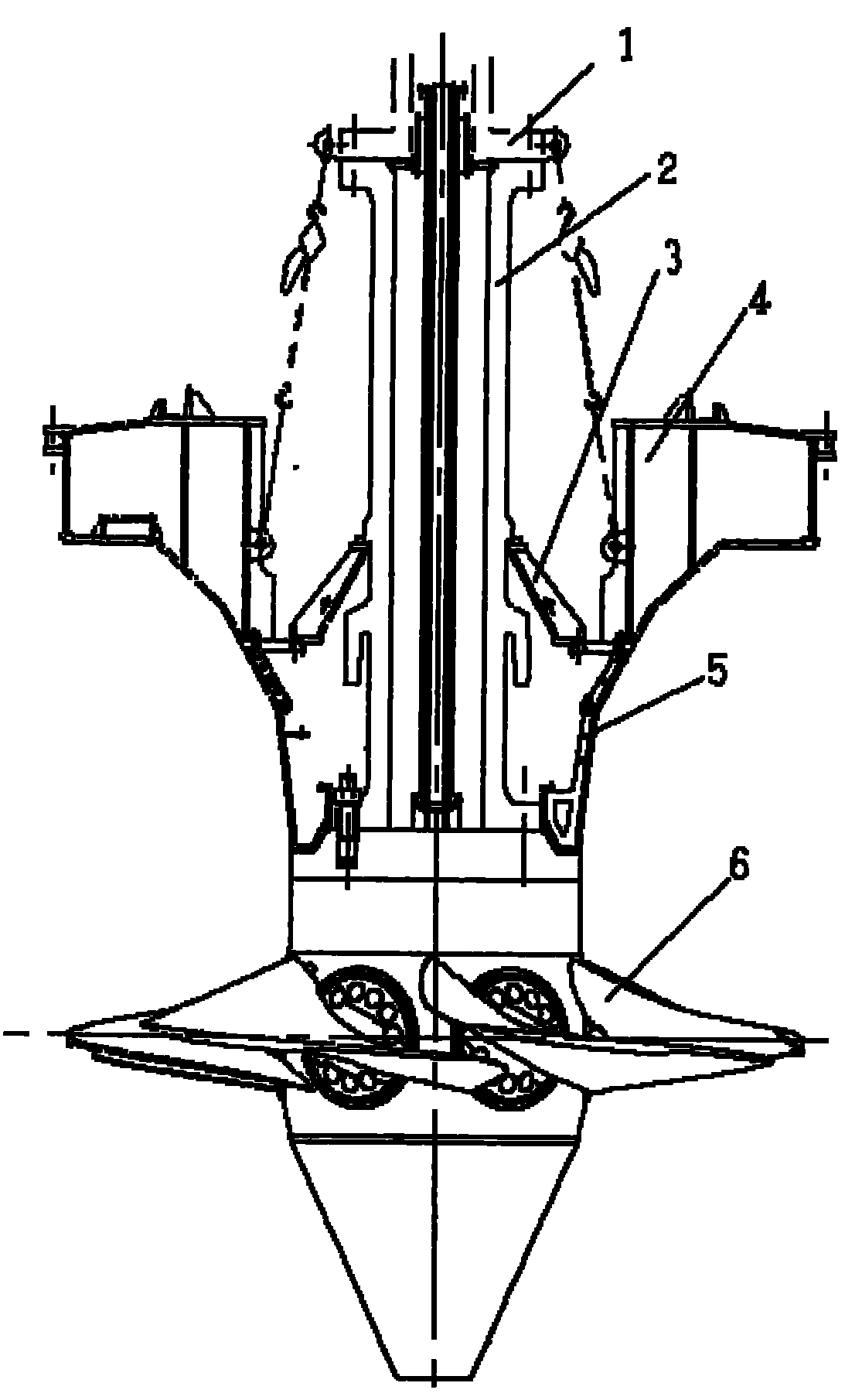
[0010] Such as figure 1 As shown in the figure, the runner hoisting process of the vertical shaft axial flow turbine, put the installed runner 6 on the platform, and the blades are in the fully closed position; Connect the operating oil pipe with the operating oil pipe of the runner, then connect the main shaft with the runner, and pre-tighten the connecting bolts of the runner; 3. Combine the support cover 4 and the diversion cone 5 and insert them into the main shaft or the support cover 4 and the diversion cone 5 Put them in respectively and put them together, and place them on the upper flange of the runner body or on the runner cover. There are snap rings in half; 5. Use a gourd to adjust the upper and lower heights of the combination of the support cover 4 and the diversion cone 5, which is convenient for coupling, and at the same time plays a role of safety protection when the whole is hoisted in...


PUM


Abstract

The invention relates to a hoisting process for a rotating wheel of a vertical shaft axial flow hydraulic turbine, which comprises the following steps of: 1, arranging a small convex plate at the appropriate position on a main shaft; 2, putting an installed rotating wheel on a platform in an installation room, allowing blades to be in the complete shut-down position, and adjusting the horizontal of an upper flange surface of the rotating wheel by 0.02mm/m; 3, hoisting a combining piece of the main shaft and an operating oil tube, connecting the operating oil tube with an operating oil tube of the rotating wheel, connecting the main shaft with the rotating wheel, and connecting the rotating wheel with a bolt and pretightening; 4, sleeving the combination body into the main shaft after combining a support cover and a flow guiding cone or combining the support cover and the flow guiding cone after sleeving the support cover and the flow guiding cone into the main shaft respectively, and putting the combination body on an upper flange or a rotating wheel cover of a rotating wheel body; 5, arranging a partitioned bearing on the support cover or the flow guiding cone, and arranging a divided clamping ring on the top of the bearing; 6, adjusting the height of combination body of the support cover and the flow guiding cone by using a hoist and conducting the safe and protective action when the combination body is hoisted in a turbine pit integrally; 7, reserving an axial gap between the convex plate on the main shaft in the installation room and the clamping ring, wherein the gap is 2 to 5 millimeters greater than the sum of a reverse machine lift value and a bayonet value of the main shaft, and the value is 2 to 5 millimeters greater than the bayonet value of the main shaft, so that the coupling is convenient; and 8, arranging a hanger, and hoisting the combination body in the turbine pit to be put in place.

Description

Technical field: [0001] The invention relates to a process for hoisting a runner of a vertical shaft axial flow water turbine. Background technique [0002] Such as Figure 1 As shown, the traditional hoisting method for the runner of the vertical shaft axial flow turbine is to provide a suspension hole on each blade, and to set a support ring 6 on the base ring or the upper ring of the runner chamber to connect the runner suspension tool 4 and Part 12, so that the runner passes through the suspension hole on the blade, the suspension tool, and the foundation ring to connect the runner to achieve the purpose of suspending the runner in the runner chamber, and then carry out the main shaft and rotation of the turbine in the machine pit. Wheel connection, this kind of hoisting method was basically adopted in China before the 1990s, so the design and use of this hoisting method are very mature. However, with years of inspection of the sports unit, it is generally reported that...

Claims


Application Information

Patent Timeline
IPC IPC(8): B66F19/00
Inventor 朱再华章焕能朱何会
Owner 浙江富春江水电设备股份有限公司
Why Eureka
Try Eureka