
Method for monitoring Lamb wave engineering structural damage by utilizing signal decomposition
A technology for engineering structure and damage monitoring, which is applied in the analysis of solids using sound waves/ultrasonic waves/infrasonic waves, and can solve problems such as fast signal absorption, deviations, and interference with the correct extraction of damage scattering signals
- Summary
- Abstract
- Description
- Claims
- Application Information
AI Technical Summary
Problems solved by technology
Method used
Image

Examples
Embodiment Construction
[0035] The implementation process of the present invention will be described in detail below in conjunction with the accompanying drawings.
[0036] The invention provides a Lamb wave engineering structure damage monitoring method utilizing signal decomposition, comprising the following steps:
[0037] (1) Arrange a group of piezoelectric elements on the engineering structure to be monitored to form a sensing / excitation array, where the piezoelectric element used as the excitation element is set to P j , and the piezoelectric element as the sensing element is set to P i ,and i,j =1,2,3,...;
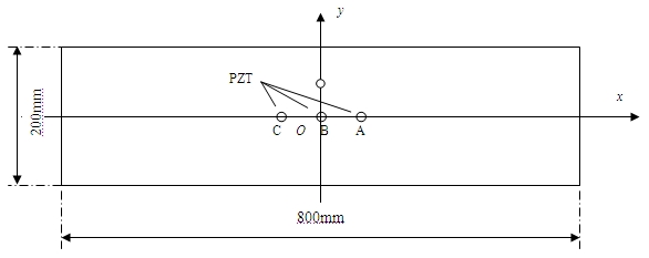
[0038] In this example, with figure 1 As shown, take i =1, 2, j =1, the three piezoelectric elements are all fixed on the test piece, the said test piece is an epoxy glass fiber reinforced composite material plate, the size is 800mm×200mm×2mm; the three piezoelectric elements are arranged in a straight line, to test The center point of the part is the coordinate origin, and the c...
PUM
 Abstract
Description
Claims
Application Information