Reflection type liquid crystal display device

一种液晶显示装置、反射型的技术,应用在光学、仪器、非线性光学等方向,能够解决液晶层113光透过率下降、不能得到高品质的黑显示等问题,达到提高明亮度、驱动电压抑制、提高散射效率的效果

Active Publication Date: 2011-07-20
SHARP KK
View PDF8 Cites 2 Cited by
  • Summary
  • Abstract
  • Description
  • Claims
  • Application Information

AI Technical Summary

Problems solved by technology

If the voltage applied to the liquid crystal layer 113 is insufficient, the light transmittance of the liquid crystal layer 113 will decrease, and high-quality black display cannot be obtained.

Method used


Image

  • Reflection type liquid crystal display device
  • Reflection type liquid crystal display device
  • Reflection type liquid crystal display device

Examples


Embodiment Construction

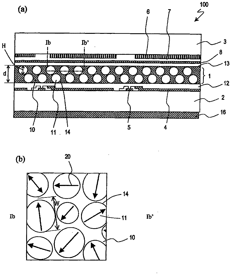
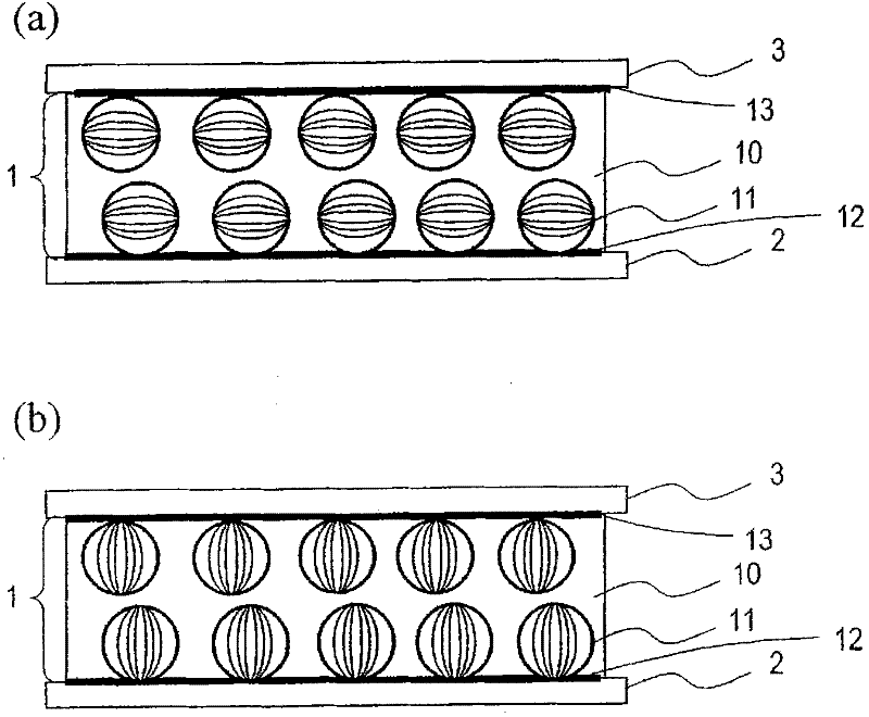
[0056] The reflective liquid crystal display device of the present invention includes at least two liquid crystal domains in one pixel, wherein the two liquid crystal domains have directors in a plane parallel to the liquid crystal layer, and the directors of these liquid crystal domains are oriented in different directions.

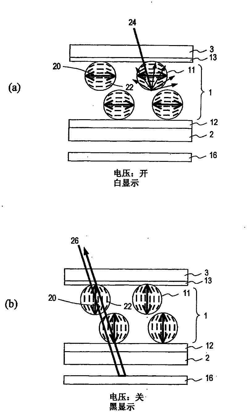
[0057] According to the present invention, the directors of the liquid crystal domains are located in the plane parallel to the liquid crystal layer. Therefore, in the scattering state (white display), the difference in refractive index from the walls separating the liquid crystal domains can be maximized, and more Bright display. Alternatively, the liquid crystal layer can be thinned while maintaining the brightness of the display, and as a result, the driving voltage can be kept low.

[0058] In addition, since the directors of the plurality of liquid crystal regions face different directions in the plane, the azimuth dependence of the scattering direc...


PUM

PropertyMeasurementUnit
surface free energyaaaaaaaaaa
diameteraaaaaaaaaa
widthaaaaaaaaaa

Abstract

Provided is a reflection type liquid crystal display device comprising a liquid crystal layer (1), which can be switched between a transmission state and a scattering state, a front substrate (3) and a back substrate (2) for holding the liquid crystal layer (1) inbetween, a pair of electrodes (4 and 8) arranged across the liquid crystal layer (1) for applying a voltage to the liquid crystal layer(1), and first and second orientation films (13 and 12) formed between the liquid crystal layer (1), and the front substrate (3) and the back substrate (2), respectively. The liquid crystal layer (1)includes, for each pixel, a continuous wall (10), a plurality of small chambers (14) separated by the wall (10), and a plurality of liquid crystal regions (11) individually formed in any of the smallchambers (14). The liquid crystal regions (11) have first and second liquid crystal regions (11) having directors (20) in a plane parallel to the liquid crystal layer (1). The directors (20) of the first and second liquid crystal regions (11) are oriented in directions different from one another.

Description

technical field [0001] The present invention relates to a reflective liquid crystal display device. Background technique [0002] In conventional reflective liquid crystal display devices, display modes such as TN (Twisted Nematic: twisted nematic) mode and STN (Super Twisted Nematic: super twisted nematic) mode are used. However, when these display modes are used, it is necessary to arrange a polarizing plate on the surface of the liquid crystal panel, and there is a problem that light utilization efficiency decreases due to light absorption by the polarizing plate. [0003] Therefore, as a new display mode that does not require a polarizing plate, it has been proposed to perform display by switching the state between a scattering state that scatters light and a transmission state that transmits light by applying a voltage to the liquid crystal layer. mode (hereinafter referred to as "scatter-transmission mode"). In this display mode, for example, a polymer dispersed liqu...

Claims


Application Information

Patent Timeline
Patent Type & Authority Applications(China)
IPC IPC(8): G02F1/1334G02F1/1335G02F1/1337
CPCG02F1/1334G02F1/1337G02F2001/133765G02F1/133305G02F1/133553G02F1/133765G02F1/1335
Inventor 浅冈康佐藤英次箕浦洁藤原小百合
Owner SHARP KK
Why Eureka
Try Eureka