High-power illuminating device assembled by low-power LEDs (Light Emitting Diodes)

A lighting device and low-power technology, which is applied in the direction of lighting devices, lighting device components, lighting device cooling/heating devices, etc., can solve the problems of high cost, easy damage, too fast, etc., to ensure the design life and price Reasonable cost, overcome the effect of fast light decay

Inactive Publication Date: 2011-08-10
丁德培
View PDF0 Cites 2 Cited by
  • Summary
  • Abstract
  • Description
  • Claims
  • Application Information

AI Technical Summary

Problems solved by technology

However, under the current technical conditions, low-power LEDs cannot be used in high-density concentrated use to achieve high-power lighting in applications. The reason is that low-power LEDs are densely welded on circuit boards to form high-power (total power exceeding 10W) ​​lighting. When the device is in use, there is a difficult problem, that is, the heat generated by the LED cannot be conducted and diffused in a timely and effective manner, resulting in an excessively high temperature rise of the LED, which is easily damaged and seriously affects the service life of the LED. The high-density application and high-power lighting of power LEDs are limited; because of the above-mentioned difficult problems, professionals in the field even assert that it is impossible to make high-power lighting devices through dense connections of low-power LEDs
[0003] Therefore, at present, street lamps, advertising lamps and other lighting lamps that use LEDs as light sources all use high-power tubes of more than 1W. However, such high-power LED tubes have disadvantages such as low luminous efficiency and high cost, and cannot be truly marketed.

Method used


Image

  • High-power illuminating device assembled by low-power LEDs (Light Emitting Diodes)
  • High-power illuminating device assembled by low-power LEDs (Light Emitting Diodes)
  • High-power illuminating device assembled by low-power LEDs (Light Emitting Diodes)

Examples


Embodiment Construction

[0020] Below in conjunction with embodiment, the present invention will be further described.

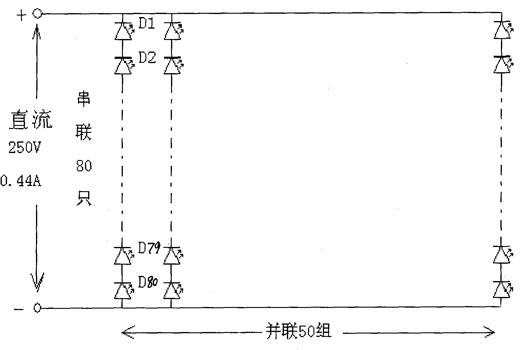
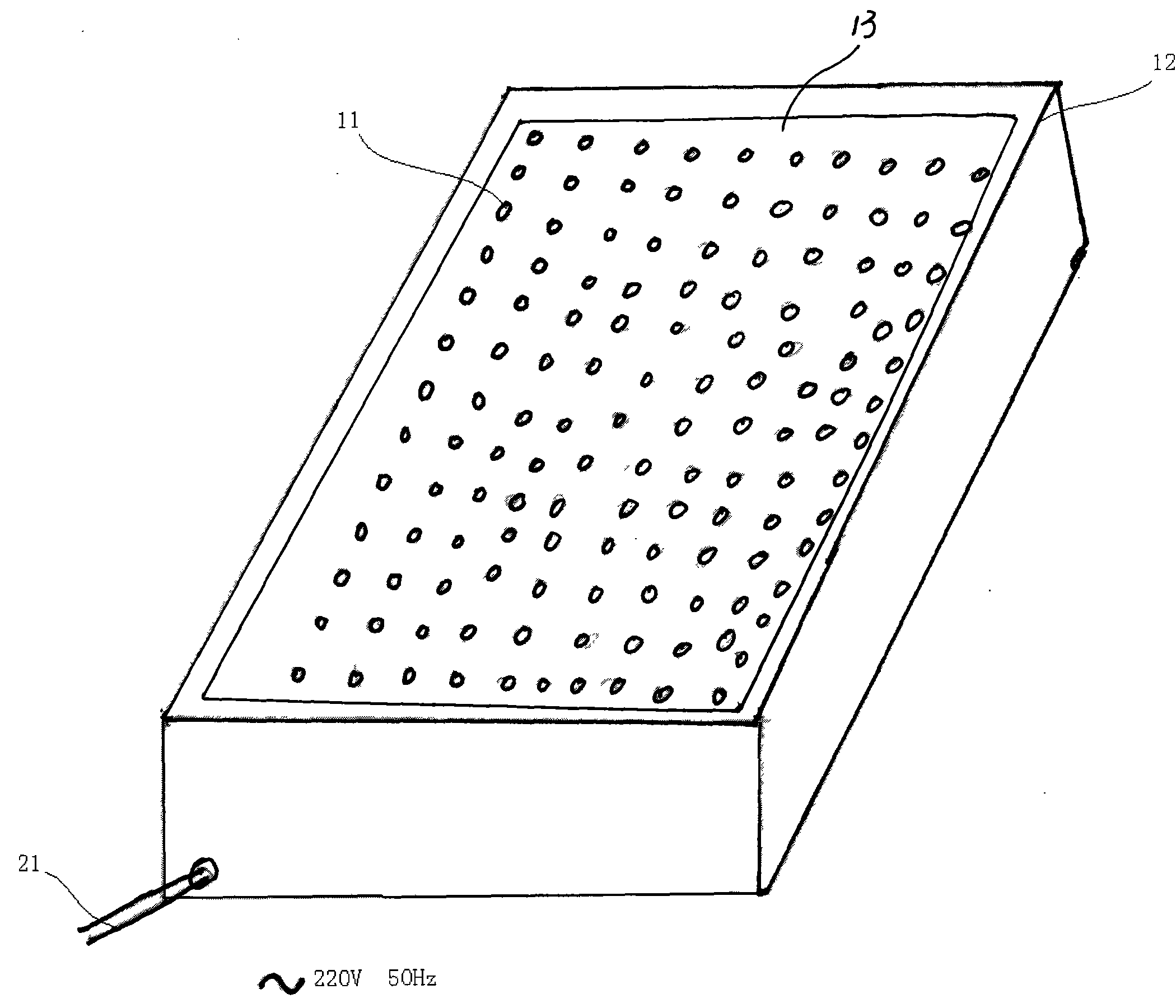
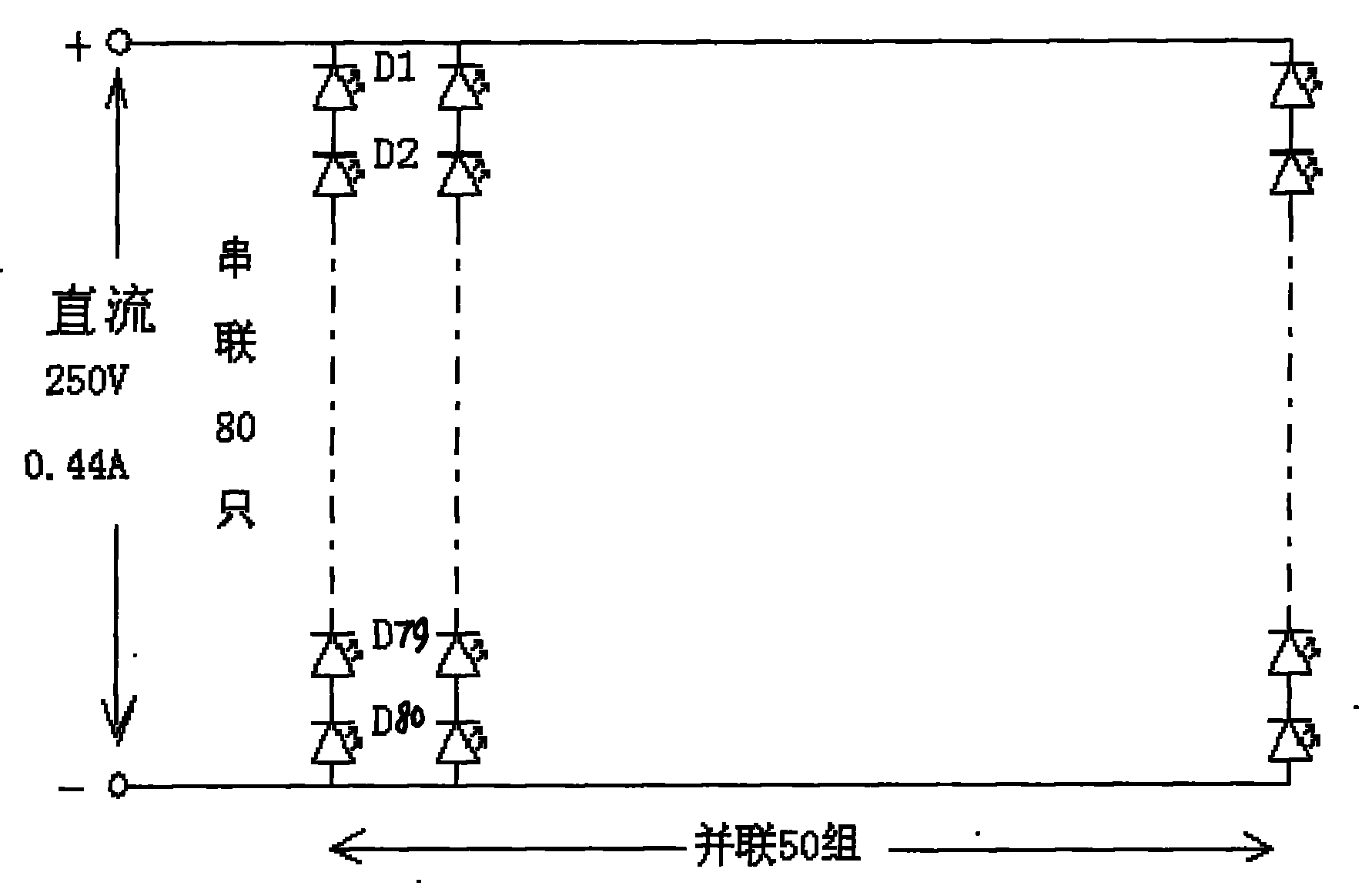
[0021] Such as figure 1 , figure 2 As shown, a LED lighting device is designed and assembled, including a DC constant voltage power supply fixed in a frame 12, a circuit board 13 for inserting a plurality of LEDs 11, and a heat sink. The DC constant voltage power supply is electrically connected to the The LED provides power, wherein: the DC constant voltage power supply can be a common switching power supply provided on the market at present, and the following conditions can be met: the provided voltage is 250 volts, and the provided current is 0.44-1.1 ampere. The connection method of the LEDs 11 inserted on the circuit board is as follows: the first number of LEDs connected in series form an LED light group, and then the second number of the LED light groups are connected in parallel to form a complete LED light module circuit, wherein the first number A quantity should meet t...


PUM


Abstract

The invention provides a high-power illuminating device assembled by low-power LEDs (Light Emitting Diodes). The invention relates to an LED illuminating device which comprises a direct-current constant-voltage power supply, a circuit board for high-density plug-in LEDs and a heat radiation device, wherein the voltage provided by the direct-current constant-voltage power supply is 250 volt, and the current provided is 0.44-1.1 ampere; the connection manner of the LEDs inserted on the circuit board is that a first quantity of LEDs are connected in series to form an LED lamp bank, then a second quantity of LEDs are connected in parallel to form a whole LED lamp module circuit, wherein the first quantity of LEDs has to meet the condition that the voltage sum of the first quantity of serially-connected LEDs is equivalent to 250 volt; and the second quantity of LEDs is determined according to the total power required by the LED illuminating device. The high-power illuminating device overcomes a series of defects that a high-power LED street lamp has quick light decay, insufficient brightness and high price, is easy to damage and the like and has the advantages of high brightens, high reliability and reasonable cost, and the power factor is kept within the scope of 0.95-0.98.

Description

technical field [0001] The invention relates to the field of LED lamps, in particular to a high-power lighting fixture composed of a plurality of low-power LEDs. technical background [0002] At present, LEDs used in the field of lighting have become the key development direction of green lighting in the world because of their high luminous efficiency, cold light source, and green environmental protection. However, under the current technical conditions, low-power LEDs cannot be used in high-density concentrated use to achieve high-power lighting in applications. The reason is that low-power LEDs are densely welded on circuit boards to form high-power (total power exceeding 10W) ​​lighting. When the device is in use, there is a difficult problem, that is, the heat generated by the LED cannot be conducted and diffused in a timely and effective manner, resulting in an excessively high temperature rise of the LED, which is easily damaged and seriously affects the service life o...

Claims


Application Information

Patent Timeline
Patent Type & Authority Applications(China)
IPC IPC(8): F21S2/00F21V23/00F21V29/00F21V29/02H05B37/00F21Y101/02F21K9/20F21V29/67F21V29/74F21Y115/10
Inventor 丁德培
Owner 丁德培
Why Eureka
Try Eureka