Supercharge Your Innovation With Domain-Expert AI Agents!

Blade of a wind turbine

A technology of wind turbines and blades, applied to wind engines, wind turbine components, blades, etc., can solve expensive and time-consuming problems, achieve the effect of reducing weight, reducing quantity, and avoiding repair work

Inactive Publication Date: 2011-11-23
SIEMENS AG
View PDF5 Cites 0 Cited by
  • Summary
  • Abstract
  • Description
  • Claims
  • Application Information

AI Technical Summary

Problems solved by technology

This work is time consuming and expensive

Method used


Image

  • Blade of a wind turbine
  • Blade of a wind turbine
  • Blade of a wind turbine

Examples


Embodiment Construction

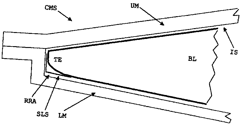
[0031] figure 1 The arrangement created to be part of the closed mold system CMS is shown by means of a cross-sectional view.

[0032] The lower mold LM is used in the VARTM process to support the blade BL of the wind turbine.

[0033] The structure of the blade BL is built by fibers, mats, balsa wood, prefabricated parts, bladders filled with any kind of shaped material etc. (not shown in detail here) as described above. These elements thus form the different layers of the wind turbine blade.

[0034] Therefore, the lower mold LM is used to support this "sandwich structure" of the blade BL.

[0035] The upper mold UM is connected to the lower mold LM, and the upper mold UM is also used to build the closed mold structure, as described above.

[0036] The cross-sectional view shows the trailing edge TE of the blade BL.

[0037] Due to the inner surface IS of the closed mold structure and due to the specific shape of the trailing edge TE, a resin rich area RRA will be create...


PUM


Abstract

A blade of a wind turbine is provided. The blade includes different layers, which are used to build up the three-dimensional shape of the blade. Resin is applied to connect the layers while the blade is manufactured. A reinforcement structure is arranged close to the surface of the blade and at a resin-rich-section of the blade, where a certain amount of resin is gathered during the manufacture of the blade.

Description

technical field [0001] The invention relates to blades for wind turbines. Background technique [0002] Modern wind turbine blades are usually manufactured by means of the so-called "Vacuum Assisted Resin Transfer Molding, VARTM" process. [0003] For this purpose, numerous layers are laid down onto a so-called "lower form" in order to build up the three-dimensional shape of the blade, wherein said layers contain fibres, mats, balsa wood, prefabricated parts, air cells filled with any kind of forming material, etc. The lower form is used to support the "sandwich structure" of the blade. [0004] The lower mold is connected to the "upper mold" to form a closed mold structure. The mold covers or better encapsulates the blade structure. [0005] In the VARTM process, a process vacuum is applied to a closed mold structure, thereby evacuating air from this structure and simultaneously infusing resin into the structure accordingly. [0006] The resin is allowed to cure and the...

Claims


Application Information

Patent Timeline
Patent Type & Authority Applications(China)
IPC IPC(8): F03D11/00
CPCB32B1/00B29L2031/085B32B3/08B32B21/045Y02E10/721F05B2280/6015B32B3/02B32B21/042B32B2260/026B32B5/26F05C2253/22B32B2260/048B32B2603/00B32B2260/046F05B2280/702F03D1/065B32B2260/023F05C2253/20Y02E10/72Y02P70/50
Inventor J.J.O.克里斯滕森M.诺尔莱姆
Owner SIEMENS AG
Features
  • R&D
  • Intellectual Property
  • Life Sciences
  • Materials
  • Tech Scout
  • Unparalleled Data Quality
  • Higher Quality Content
  • 60% Fewer Hallucinations
Learn More