Al technical title is built by PatSnap Al team. It summarizes the technical point description of the patent document.
A circulator and shell technology is applied in the field of nanomaterial production equipment, which can solve the problems of high cost of nanomaterial manufacturing, inability to produce particle size nanomaterials, and inability to use nanomaterials in large quantities, so as to save material consumption and shorten construction. time, the effect of improving structural strength and service life
Inactive Publication Date: 2012-03-21
陈久斌
View PDF0 Cites 3 Cited by
Summary
Abstract
Description
Claims
Application Information
AI Technical Summary
This helps you quickly interpret patents by identifying the three key elements:
Problems solved by technology
Method used
Benefits of technology
Problems solved by technology
[0008] Existing nanomaterial production equipment has defects such as inability to produce smaller and more uniform nanomaterials
Nanomaterials are expensive to manufacture, so nanomaterials with excellent performance cannot be widely used
Method used
Image
Click on the blue label to locate the original text in one second.
Reading with bidirectional positioning of images and text.
Examples
Embodiment Construction
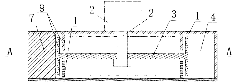
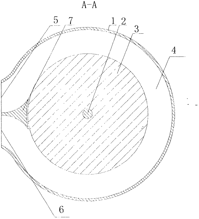
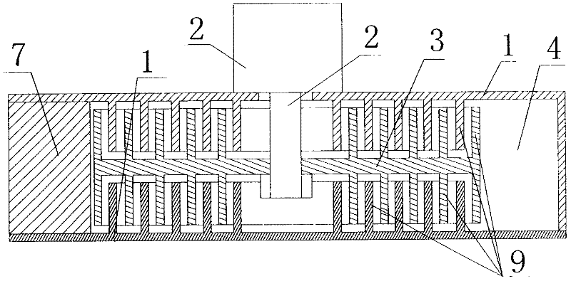
[0044] The main structure of the circulator of the present invention includes a housing 1 and a transmission device 2, the transmission device 2 is installed on the housing 1, the runner 3 is installed on the transmission device 2, the runner 3 is arranged in the housing 1, and the outer shell of the runner 3 A circulation chamber 4 is provided on the inner wall of the body 1, one end of the circulation chamber 4 is provided with an A circulation chamber opening 5, the other end of the circulation chamber 4 is provided with a B circulation chamber opening 6, and the housing between the A circulation chamber opening 5 and the B circulation chamber opening 6 1. An insulator 7 is arranged on the inner wall, and the insulator 7 is close to the outer edge of the runner 3.
[0045] The scope of the casing 1 includes a machine base, a casing, a power device or a force device, etc., and each part can be collectively referred to as a casing. The housing can also be integrated with the ...
PUM
Abstract
The invention relates to a circulator, comprising a housing and a transmission gear, wherein a circulation cavity is arranged in the housing; a transmission gear is mounted on the housing; a rotating wheel is arranged in the housing; the transmission gear and the rotating wheel are connected with each other, the circulating cavity is internally provided with a circulating cavity inlet and a circulating cavity outlet; the circulating cavity expands gradually from one end to the other end, and an isolator is arranged in the housing between the circulating cavity inlet and the circulating cavity outlet. The circulator makes full use of circular motion and fluid motion, can better convert torsion force into pressure or thrust force through fluid, and better convert pressure or thrust force into torsion force through fluid. Moreover, particle mixing is realized through eddy flow, and chemical reaction becomes more sufficient by utilizing eddy flow. The circulator can be used as water pumps, slurry pumps, sewage pumps, blower fans, compressors, spraying equipment, atomizers, reactors, water turbines, steam turbines, wind turbines, vacuum equipment, foam material production equipment, nanometer material equipment and the like. The circulator provided by the invention has the advantages of high efficiency, low abrasion, etc., can be used for manufacturing fire-new foam material, and can usher in material revolution.
Description
technical field [0001] The present invention relates to fluid pressurization equipment, fluid suction equipment, spray equipment, reactor equipment, water turbine equipment, steam turbine equipment, wind turbine, engine waste heat utilization turbocharger, vacuum equipment, foam material production equipment, nano material production equipment, etc. field, specifically a circulator. It can be widely used in the fields of fluid pressurization, transportation, suction and the like. It can be used as water pump, booster pump, self-priming pump, slurry pump, mud pump, dredging pump, air pump, fan, air compressor, vacuum pump, etc., which can generate high pressure and suction. Also works as a nebuliser, producing a high-pressure, ultra-fine mist. It can also be used as a reactor, which can form a special reaction condition environment in the circulator to better complete the chemical reaction. It can also be used as a new type of water turbine, steam turbine, wind turbine, engi...
Claims
Application Information
Patent Timeline
Application Date:The date an application was filed.
Publication Date:The date a patent or application was officially published.
First Publication Date:The earliest publication date of a patent with the same application number.
Issue Date:Publication date of the patent grant document.
PCT Entry Date:The Entry date of PCT National Phase.
Estimated Expiry Date:The statutory expiry date of a patent right according to the Patent Law, and it is the longest term of protection that the patent right can achieve without the termination of the patent right due to other reasons(Term extension factor has been taken into account ).
Invalid Date:Actual expiry date is based on effective date or publication date of legal transaction data of invalid patent.