Butt joint device and butt joint method for building fireproof door walls

A docking device, door and wall technology, applied in the direction of architecture, building structure, window sill/threshold, etc., can solve the problems of wafer damage, overall unevenness, and inability to ensure wafer safety.

A docking device, door and wall technology, applied in the direction of architecture, building structure, window sill/threshold, etc., can solve the problems of wafer damage, overall unevenness, and inability to ensure wafer safety.

CN102465587BActive Publication Date: 2014-01-08CSMC TECH FAB2 CO LTD

Image

  • Butt joint device and butt joint method for building fireproof door walls
  • Butt joint device and butt joint method for building fireproof door walls

Examples


Embodiment Construction

[0022] The specific implementation manners of the present invention will be described in detail below in conjunction with the accompanying drawings.

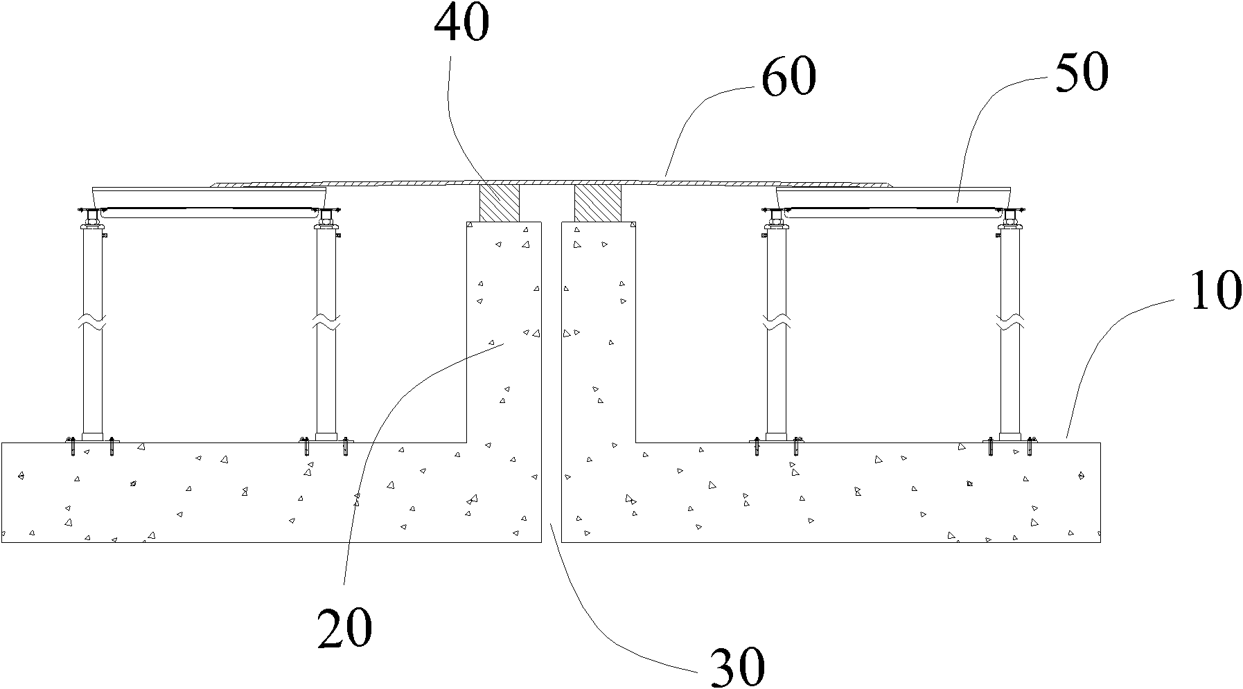
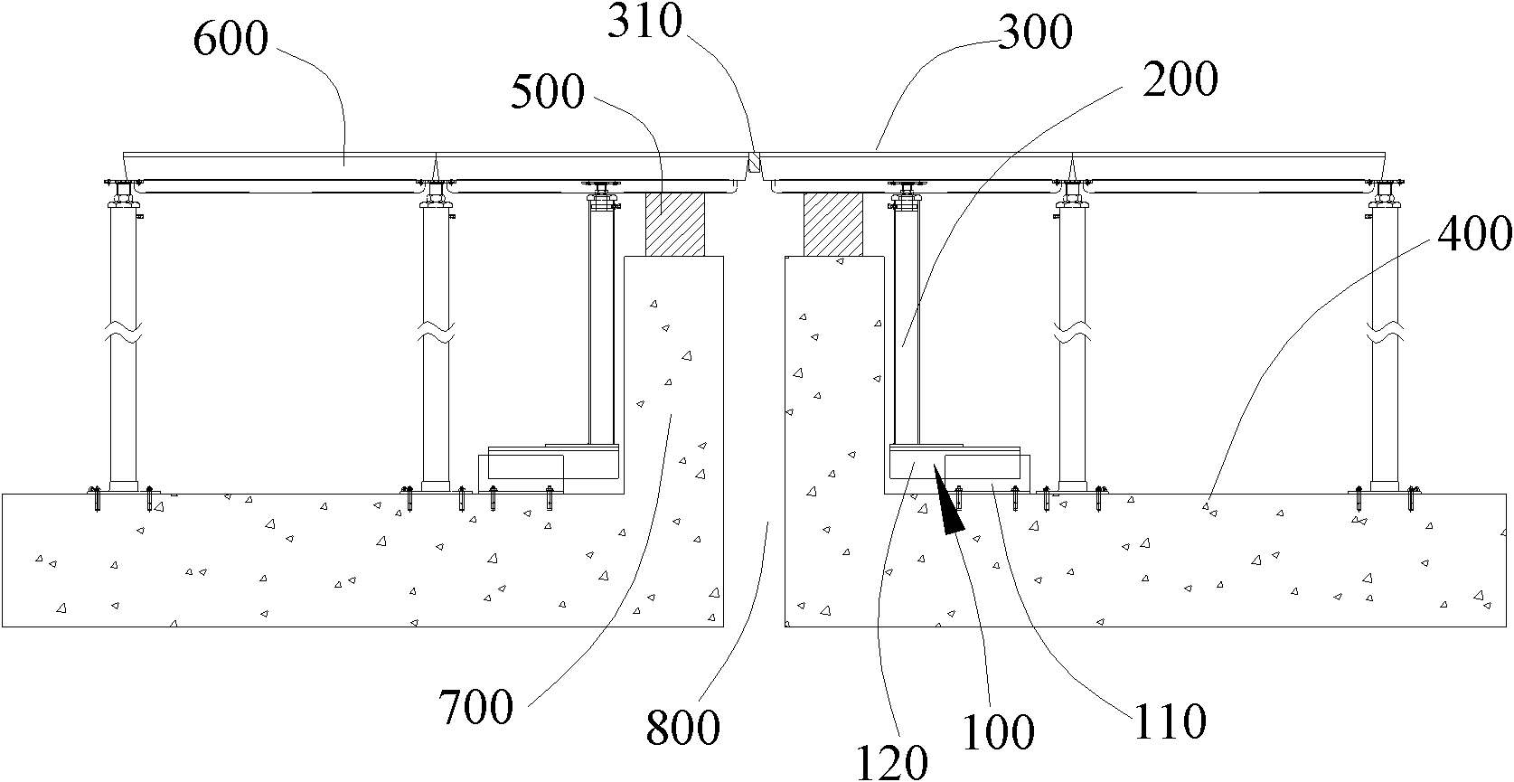
[0023] When the docking device is installed, in some cases, the thresholds erected on the fire door walls of two adjacent buildings may first be processed to reduce the height of the thresholds so that the height of the processed thresholds is lower than the height of the installed raised floor, so that the docking The device can be erected on the building fire door wall and docked horizontally with the installed raised floor.

[0024] figure 2 It is a structural schematic diagram of a docking device for a building fire door wall in an embodiment. There are two sets of docking devices, which are located on both sides of the expansion joint 800 and between the building fire door wall 700 and the installed raised floor 600 . The floor support leg assembly 100 and the floor support column 200 form a supporting mechanism for supp...


PUM


Abstract

The invention relates to a butt joint device and a butt joint method for building fireproof door walls. The device is communicated with installed overhead floors on two sides of the building fireproof door walls; and an expansion joint is formed between the two building fireproof door walls on the ground. The device comprises a butt joint floor and a support mechanism for supporting the butt joint floor, wherein the butt joint floor is subjected to horizontal butt joint together with the installed overhead floors on the two sides under the support action of the support mechanism. In the device, the butt joint floor is subjected to the horizontal butt joint together with the installed overhead floors, the butt joint floor and the installed overhead floors are positioned on the same horizontal plane, and a height difference between the butt joint floor and the installed overhead floors is avoided, so that a cart can pass through the building fireproof door walls stably without vibration, and the safety of circular sheets is ensured.

Description

【Technical field】 [0001] The invention relates to a docking device and a docking method of a building fire door wall, in particular to a butt joint device and a docking method of a building fire door wall in a purification plant. 【Background technique】 [0002] The elevated docking floor of the clean room in the semiconductor purification plant needs to ensure a certain degree of levelness to ensure that the carts pushing the wafers run smoothly. [0003] Such as figure 1 Shown is a schematic diagram of a traditional clean room. Usually, there is an expansion joint 30 between two building fire door walls 20 on the ground 10, and a threshold 40 needs to be erected on the building fire door walls. Owing to having sill 40 and expansion joint 30, in order to keep expansion joint 30 function and cart can pass, mostly adopt a slope-shaped steel plate 60 to add cover on the raised floor 50 installed on both sides of building fire door wall, carry out transition. However, the slop...

Claims


Application Information

Patent Timeline
08 Jan 2014
Publication
CN102465587B
IPC
E04F15/02; E06B1/70
Inventors
孙景艳