Apparatus for ophthalmological laser surgery

An ophthalmic laser and equipment technology, applied in ophthalmic surgery, laser surgery and other directions, can solve the problem of inaccurate incision guidance and so on

Inactive Publication Date: 2012-05-23
WAVELIGHT GMBH
View PDF5 Cites 3 Cited by
  • Summary
  • Abstract
  • Description
  • Claims
  • Application Information

AI Technical Summary

Problems solved by technology

With reduced manufacturing precision of the contact elements, this can lead to imprecise incision guidance in the eye tissue along the z-direction

Method used


Image

  • Apparatus for ophthalmological laser surgery
  • Apparatus for ophthalmological laser surgery

Examples


Embodiment Construction

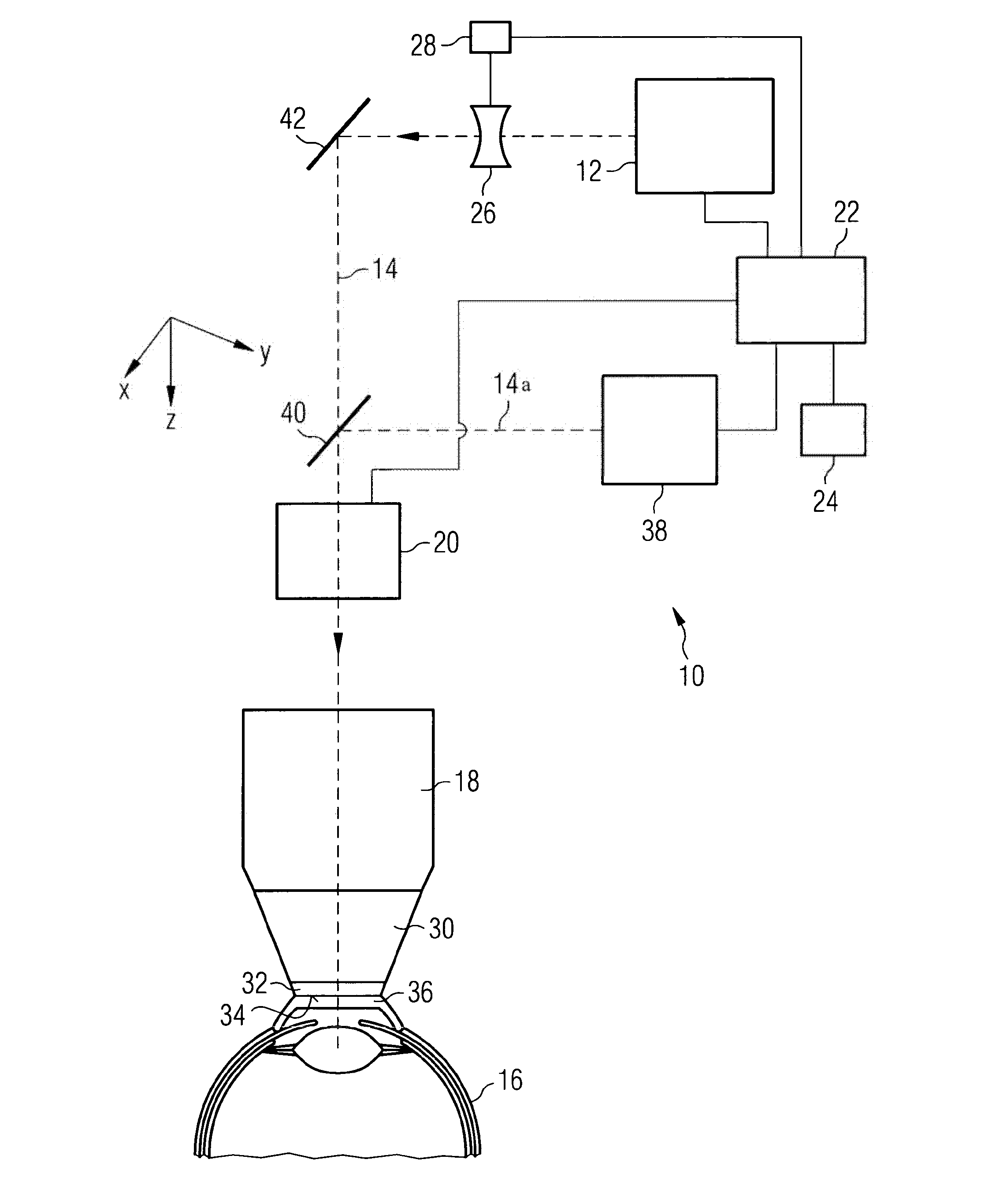
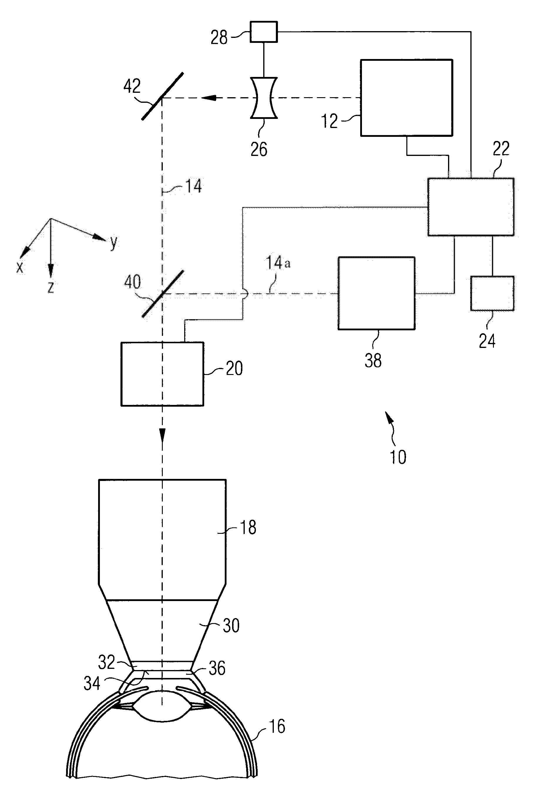
[0019] In the following, the invention is explained in more detail with reference to the single drawing. Figure 1 shows an embodiment of an apparatus for ophthalmic laser surgery in a very schematic form. The laser surgery device is indicated generally at 10 . The laser surgery apparatus includes a femtosecond (fs) laser 12 that emits pulsed laser radiation with a pulse width on the order of femtoseconds. The laser radiation travels along a beam path 14 and ultimately reaches the eye 16 to be treated. Various components for guiding and shaping the laser radiation are arranged in the beam path 14 . In particular, these components include a focusing objective 18 (such as an F-theta objective) and a scanner 20 which is connected upwards from the objective 18 and by means of which the laser radiation provided by the laser 12 can be directed perpendicular to the beam path. Deflection in the plane of 14 (x-y plane). The coordinate system drawn in this figure marks this plane, as...


PUM


Abstract

An apparatus for ophthalmological laser surgery comprises a contact surface (34), which bears with a shaping action on an eye (16) that is to be treated, components (12, 18, 20, 26, 40, 42) for providing focussed, pulsed laser treatment radiation and for directing the latter through the contact surface onto the eye, a measurement device (38) for measuring the position of the contact surface relative to the direction of propagation of the laser treatment radiation, wherein the measurement device provides position measurement data representative of the measured position of the contact surface at at least one location thereof, and an electronic evaluation and control arrangement (22), which is connected to the measurement device and which is designed to adjust the focal spot of the laser treatment radiation depending on the position measurement data. By measuring the position of the contact surface (34), the laser surgery apparatus permits compensation of unavoidable manufacturing tolerances of a contact element (32) forming the contact surface and therefore permits precise referencing of the anterior surface of the eye in relation to the laser surgery apparatus.

Description

technical field [0001] The present invention relates to equipment for ophthalmic laser surgery. Background technique [0002] Pulsed laser radiation is used in many techniques for the treatment of the human eye. In some of these techniques, the eye to be treated is brought against a transparent contact element, which, with its contact surface facing the eye, forms a path for focusing the beam along the z direction (according to customary notes, this refers to the laser beam The direction of propagation) the reference surface for positioning. In particular, therapeutic techniques for producing cuts (incisions) in eye tissue by means of focused femtosecond laser radiation often employ such contact elements as z-references for laser focusing. The contact element defines the z-position of the front surface of the eye due to the contact element being pressed against the eye in such a way that the eye becomes close, the flat support contacts the eye-facing contact surface of the...

Claims


Application Information

Patent Timeline
Patent Type & Authority Applications(China)
IPC IPC(8): A61F9/008A61F9/009
CPCA61F9/00836A61F9/009A61F2009/00872A61F9/008
Inventor 彼得·里德尔克里斯托夫·德尼茨基克劳斯·沃格勒
Owner WAVELIGHT GMBH
Why Eureka
Try Eureka