Laser surgery endoscope

A technology of laser surgery and endoscopy, which is applied in the field of medical devices, can solve problems such as damage to back-end equipment such as cameras, laser damage, and affect the quality of surgery, and achieve significant practical significance in production, avoid damage, and ensure image quality.

Inactive Publication Date: 2009-03-25
TIANJIN BOLANG SCI TECH DEV
View PDF0 Cites 4 Cited by
  • Summary
  • Abstract
  • Description
  • Claims
  • Application Information

AI Technical Summary

Problems solved by technology

Since the power used in laser therapy generally exceeds Class 3B lasers (GB7247.1-2001), ordinary endoscopes do not have protective devices and are vulnerable to laser damage, so laser surgery cannot be completed at all. Currently, there is no available laser surgery available on the market. Laser Surgical Endoscope
[0004] In order to carry out laser surgery, the current remedial method for clinical use of ordinary endoscopes in laser surgery is to install an external laser protection sheet. The disadvantage of this remedy is that the external protection sheet has no fixed installation position and can only be placed At a certain position between the endoscope and the adapter or the adapter and the Charge Coupled Device (CCD) camera, the operator needs to adjust the position of the laser protection sheet when performing the operation, so as to protect the back-end equipment such as the camera. Effective protection, otherwise the laser will damage the back-end equipment such as the camera, and even the surgical personnel
[0005] In addition, the more disadvantageous point is that the external protective sheet cannot solve the waterproofing of the lens during the operation and the fogging caused by temperature and humidity, so that the image quality formed by the endoscope and the image display system cannot meet the expected quality. The function of use has seriously affected the quality of surgery

Method used


Image

  • Laser surgery endoscope

Examples


Embodiment Construction

[0013] In order to enable those skilled in the art to better understand the solution of the present invention, the present invention will be further described in detail below in conjunction with the accompanying drawings and embodiments.

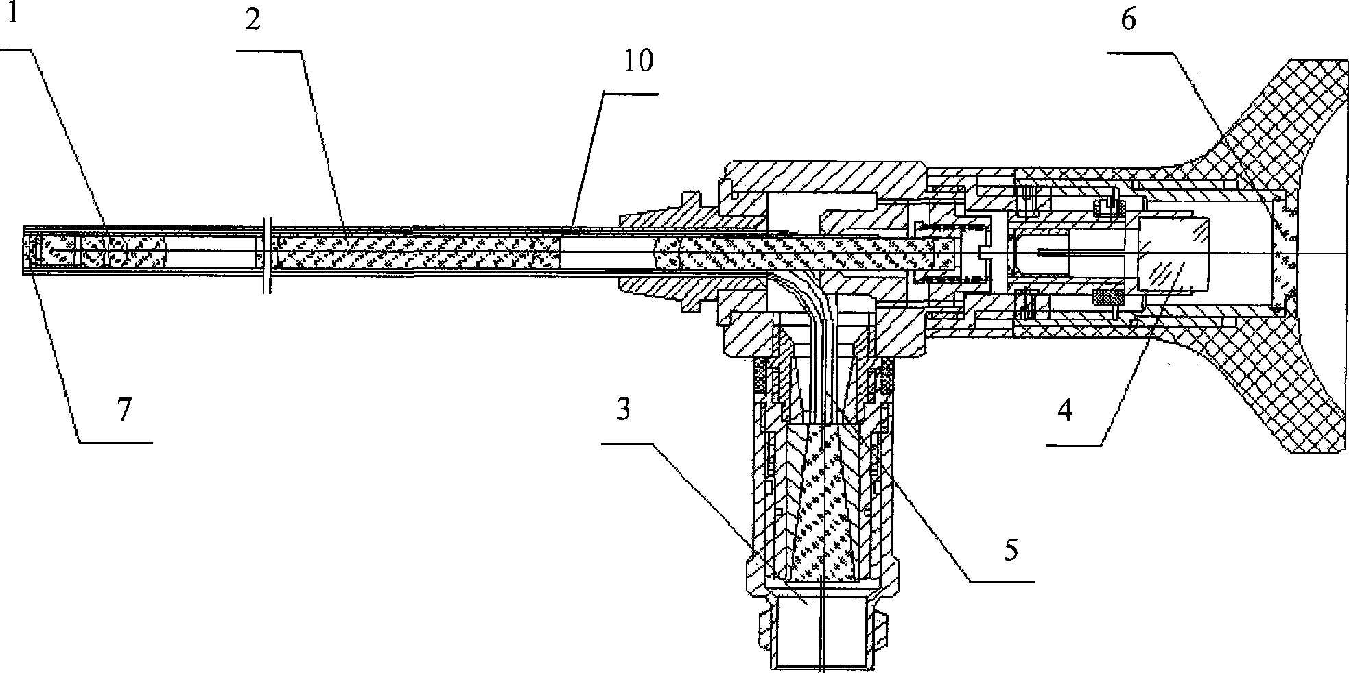
[0014] figure 1 For a structural schematic diagram of a laser surgery endoscope provided by the present invention, see figure 1 , the laser surgical endoscope provided by the present invention includes: a sealed lens barrel 10, an objective lens part 1, an image transfer system 2, a light entrance part 3, an eyepiece part 4, a light guide 5, a laser protection lens 6, and a window 7. The objective lens part 1 , the image transfer system 2 , the light entrance part 3 , the eyepiece part 4 , and the laser protection lens 6 are sequentially arranged in the sealed lens barrel 10 from left to right.

[0015] The light guide 5 is located in the sealed lens barrel 10 between the window 7 and the light entrance 3 , one end of the light guide 5 is c...


PUM


Abstract

The invention discloses a laser surgical endoscope, comprising a sealed drawtube, a field lens part, an image transferring system, a light intake part, an ocular part, a lead beam, a laser protecting lens and a window plate. The field lens part, the image transferring system, the light intake part, the ocular part, the lead beam and the laser protecting lens are arranged inside the sealed drawtube sequentially from left to right. The window plate is installed at the front end of the field lens part, and the laser protecting lens is arranged at the back end of the ocular. The lead beam is arranged inside the sealed drawtube between the window plate and the light intake part. One end of the lead beam is connected with the light intake part and the other end of the lead beam is connected with the window plate. Adopting the new design of arranging the laser protecting lens inside, the laser surgical endoscope can avoid injuries and damages to the operators and back end equipment such as a video camera and can ensure the quality of the acquired image so that the medical operators can directly carry out laser surgery under the endoscope. Therefore, the laser surgical endoscope has great practical significance for production.

Description

technical field [0001] The invention relates to the technical field of medical instruments, in particular to a laser surgical endoscope. Background technique [0002] Endoscope, referred to as endoscope for short, is a device used to directly observe the internal cavity of human organs. At present, the implementation of laser surgery under the endoscope has become the frontier means in the medical field due to its safety and efficacy. [0003] Laser therapy is the use of lasers of different wavelengths to perform efficient vaporization or lithotripsy on human lesions. Since the power used in laser therapy generally exceeds Class 3B lasers (GB7247.1-2001), ordinary endoscopes do not have protective devices and are vulnerable to laser damage, so laser surgery cannot be completed at all. Currently, there is no available laser surgery available on the market. laser surgery endoscope. [0004] In order to carry out laser surgery, the current remedial method for clinical use of...

Claims


Application Information

Patent Timeline
Patent Type & Authority Applications(China)
IPC IPC(8): A61B18/20
Inventor 齐麟张鹰
Owner TIANJIN BOLANG SCI TECH DEV
Why Eureka
Try Eureka