System for laser surgical ophthalmology

An ophthalmic laser and surgery technology, applied in the system field of ophthalmic laser surgery, can solve problems such as thermal damage to corneal tissue that cannot be ruled out

Active Publication Date: 2012-05-09
ALCON INC
View PDF6 Cites 4 Cited by
  • Summary
  • Abstract
  • Description
  • Claims
  • Application Information

AI Technical Summary

Problems solved by technology

Adjacent foci may then no longer be clearly separated from each other, but are so close togeth...

Method used


Image

  • System for laser surgical ophthalmology
  • System for laser surgical ophthalmology
  • System for laser surgical ophthalmology

Examples


Embodiment Construction

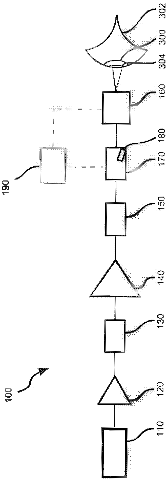
[0026] The full text is referred to by 100 and in figure 1 The system shown in schematic block diagram representation in , is a laser system suitable for internal tissue cutting in a patient's eye. Intracorneal flap ablation for creating a LASIK flap is one possible and preferred example of an ablation for which laser system 100 is suitable. However, this does not preclude the use of laser system 100 for other forms of tissue cutting in the eye.

[0027] The laser system 100 includes a laser oscillator 110 which emits laser pulses in a free-running manner with a duration in the femtosecond range and a defined repetition rate. The laser oscillator 110 may be, for example, a solid-state laser oscillator, more specifically a fiber laser oscillator. The pulses emitted by the laser oscillator 110 pass through a preamplifier device 120 which increases the pulse power. At the same time, the preamplifier device 120 causes pulse time stretching. The repetition rate of the laser pul...


PUM


Abstract

The invention relates to a system for laser surgical ophthalmology, comprising a source (110) of pulsed laser radiation having radiation parameters tuned for applying an incision in an eye tissue, particularly in the cornea, a scanner (160) for deflecting the laser radiation, and electronic control unit (190) set up for controlling the scanner according to a prescribed cut geometry, and a modulator unit (170) for modulating the laser pulse emitted by the source (110). The control unit (190) is further set up for controlling the modulator unit (170) according to a radiation deflection pattern determined for the cut geometry, such that at least one part of the laser pulse has a reduced pulse energy or is suppressed in predetermined parts of the radiation deflection pattern.

Description

technical field [0001] The present invention relates to systems for ophthalmic laser surgery. Background technique [0002] In refractive eye surgery, vision defects are corrected by intervention in the patient's eye to alter the refractive properties of the eye. In this regard, the so-called LASIK procedure (Laser In Situ Keratomileusis) is of great importance, in which first a planar corneal incision is made, as a result of which a small disc cap called a flap is produced. The flap can be folded aside to expose the underlying corneal tissue, the stroma. The stromal tissue is then ablated using a laser (usually an excimer laser) according to the resection pattern determined for each patient. The flap is then folded back; the wound heals relatively quickly. [0003] For flap cutting during LASIK, the previously used mechanical microkeratome has recently been replaced by femtosecond lasers, ie lasers that generate pulsed laser radiation with pulse durations in the femtosec...

Claims


Application Information

Patent Timeline
IPC IPC(8): A61F9/01A61F9/008B23K26/08
CPCB23K26/063B23K26/0807A61F2009/00897A61F9/00836A61F9/008A61F2009/00872B23K26/0622B23K26/082
Inventor 奥拉夫・基特尔曼克劳斯・沃格勒
Owner ALCON INC
Why Eureka
Try Eureka