Measuring device and measuring method of superconductive AC magnetic susceptibility

An AC magnetic susceptibility and measuring device technology, applied in the field of superconducting electronics, can solve the problems of high price, increase temperature measurement error, etc., and achieve the effect of slowing down the temperature change speed, reducing the temperature hysteresis effect, and reliable testing means

Active Publication Date: 2012-06-20
BEIHANG UNIV
View PDF3 Cites 18 Cited by
  • Summary
  • Abstract
  • Description
  • Claims
  • Application Information

AI Technical Summary

Problems solved by technology

This method uses the method of moving the sample rack to change the position of the sample rack and the superconducting material sample to be tested on it to obtain different temperature zones. The whole process needs to move the sample rack continuously. Due to the uncertainty of artificial movement, it will cause During a certain moving process, the amplitude of the sample rod measuring frame is too large, which causes the temperature of the superconducting sample on it to change too fast, which puts forward stricter requirements for the acquisition and processing system, and more points need to be collected in a certain process. In order to ensure that the slight changes of the measured parameters are not missed, the temperature changes too fast to increase the temperature hysteresis effect and cause temperature measurement errors
In addition, it is more expensive to measure with liquid helium

Method used


Image

  • Measuring device and measuring method of superconductive AC magnetic susceptibility
  • Measuring device and measuring method of superconductive AC magnetic susceptibility
  • Measuring device and measuring method of superconductive AC magnetic susceptibility

Examples


Embodiment Construction

[0036] The present invention will be further described in detail below in conjunction with the accompanying drawings.

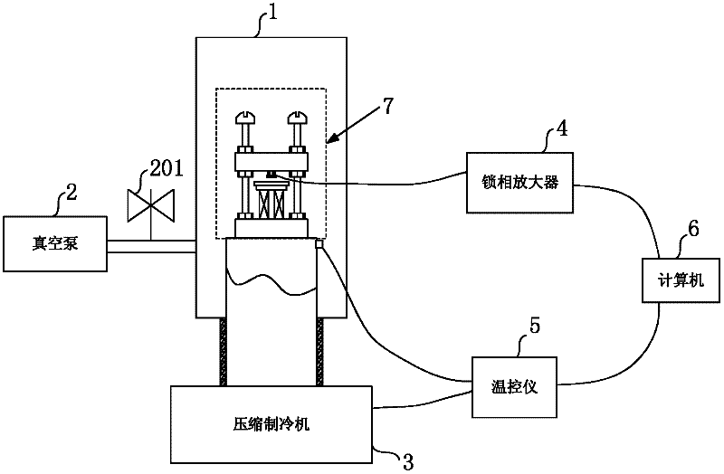
[0037] The invention is a superconducting AC magnetic susceptibility measuring device, such as figure 1 As shown, it includes a vacuum chamber 1, a vacuum pump 2, a compression refrigerator 3, a lock-in amplifier 4, a temperature controller 5, a computer 6 and a coil group 7;

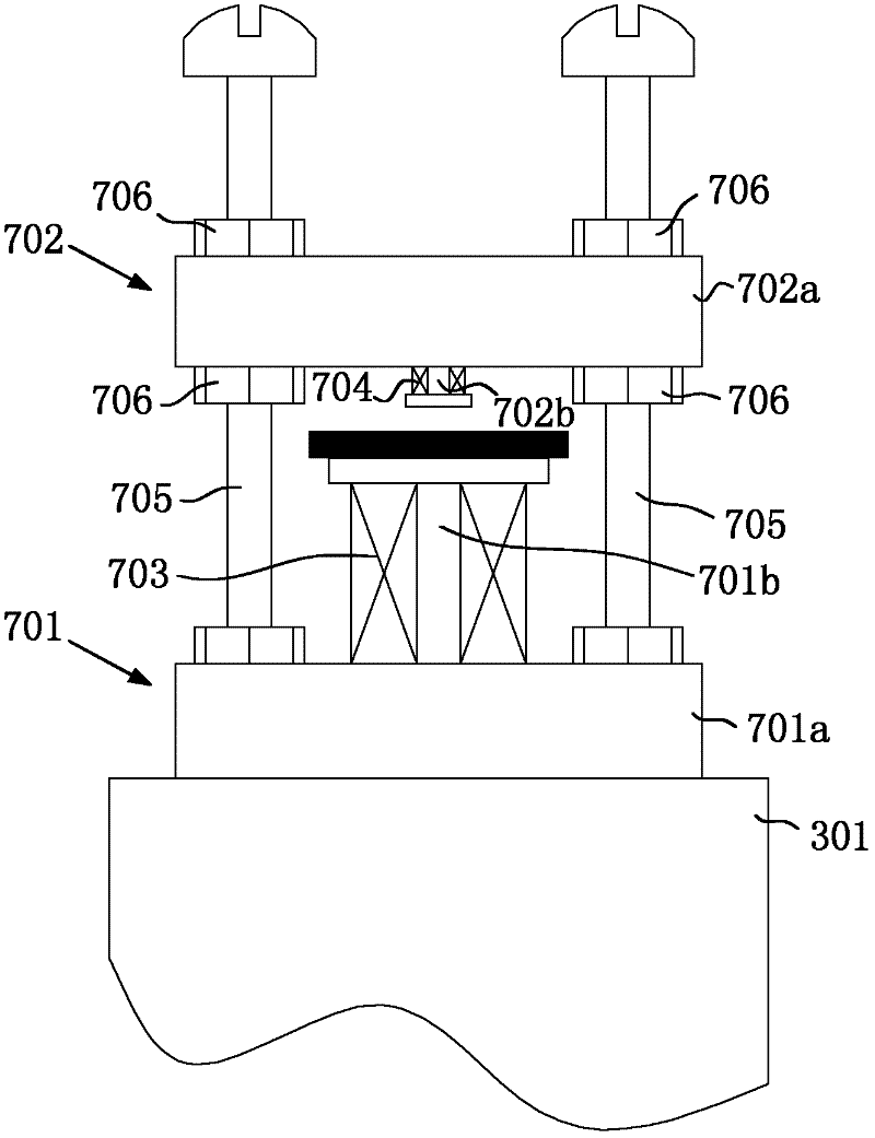
[0038] Wherein, the vacuum chamber 1 is a closed structure, the vacuum pump 2 communicates with the vacuum chamber 1 through a pipeline, and a vacuum valve 201 is installed on the pipeline. The compression refrigerator 3 has a columnar heat-conducting copper 301. The columnar heat-conducting copper 301 is used as the cooling end of the compression refrigerator, extending from the bottom of the vacuum chamber 1 into the vacuum chamber 1. heat, the compression refrigerator 3 can reduce the temperature in the vacuum chamber 1 to below 50K, which can meet the transition temperature requir...


PUM


Abstract

The invention discloses a measuring device and a measuring method of superconductive AC magnetic susceptibility, belonging to the field of superconducting electronics. The measuring method comprises the steps of: positioning a measured superconducting material between a primary coil and a secondary coil, and fixing the elements in a sealed vacuum chamber, refrigerating the measured superconducting material via a compression refrigeration machine, extracting a voltage signal induced by the secondary coil through a phase-locking amplifier, and simultaneously providing AC voltage excitation to the primary coil through the phase-locking amplifier, measuring the temperature of the measured superconducting material through a temperature controller, storing the voltage signal measured by the phase-locking amplifier and a temperature signal measured by the temperature controller in a computer, and displaying the temperatiredependent curve of the voltage signal measured by the phase-locking amplifier in real time. The measuring method of the invention has the advantages of performing a nondestructive measurement on the conversion temperature of the superconducting material to conveniently master the measurement condition in time, and the measuring method is an efficient, accurate and reliable measurement manner, so that the measuring method has certain practical value for detecting the performance of the superconducting material.

Description

technical field [0001] The invention relates to the field of superconducting electronics, specifically, a measuring device and a measuring method for non-destructively measuring the transition temperature of superconducting materials. Background technique [0002] The development of superconducting material preparation technology has been relatively mature at present, and the indicators for judging their performance include critical temperature Tc, critical current characteristic Jc, and superconducting surface microwave resistance Rc, etc. Superconducting critical temperature Tc and critical current Jc are measures of superconducting The main indicators of the performance of thin film samples, high superconducting transition temperature point and large critical current Jc are the prerequisites for the large-scale application of superconducting materials and superconducting technology. [0003] At present, there are two main methods for measuring the superconducting transiti...

Claims


Application Information

Patent Timeline
Patent Type & Authority Applications(China)
IPC IPC(8): G01N27/76G01R33/16
Inventor 王三胜褚向华程远超
Owner BEIHANG UNIV
Why Eureka
Try Eureka