Landslide depth displacement monitoring device

A monitoring device and technology of deep displacement, applied in the field of sensing, can solve the problem of not solving the effective protection of the sensing fiber sensitivity of the sensing fiber, not fully excavating and releasing the huge potential of fiber sensing, and difficult to meet the requirements of long-term real-time monitoring of landslides, etc. problems, to achieve the effect of favorable promotion and use, high practical value, and flexible use methods

Inactive Publication Date: 2012-07-11
XIAN JINHE OPTICAL TECH
View PDF0 Cites 17 Cited by
  • Summary
  • Abstract
  • Description
  • Claims
  • Application Information

AI Technical Summary

Problems solved by technology

Traditional landslide deep displacement monitoring mainly uses multi-point displacement meters and borehole inclinometers. These two instruments are not easy to carry out long-distance detection and require manual on-site monitoring. The real-time performance is poor, and it is difficult to meet the long-term real-time monitoring requirements for landslides.
Another method is to measure the deep displacement of the landslide by using the characteristic that the impedance characteristics of the coaxial cable will change with the deformation of the cable. There is no corresponding theory on the relationship between the electromagnetic wave reflection signal caused by the impedance change of the coaxial cable and the cable deformation. Therefore, the amount of deformation can only be calculated by the fitting formula of indoor repeated test results, which has great probability and is not easy to detect remotely, thus limiting its scope of use
The existing distributed optical fiber sensing technology is also tentatively applied to landslide monitoring, such as the use of optical time domain reflectometry (OTDR for short) and Brillouin backscattering technology (BOTDR for short). The contradiction between the sensitivity and the effective protection of the sensing fiber has not been widely used. In addition, the solution based on Brillouin backscattering technology has also become an important factor limiting its application due to the high cost of equipment.
The application prospect of optical fiber sensing technology in landslide monitoring is optimistic by many scholars, but the existing technical solutions have not fully tapped and released the huge potential of optical fiber sensing. These are problems that need to be solved urgently

Method used


Image

  • Landslide depth displacement monitoring device
  • Landslide depth displacement monitoring device
  • Landslide depth displacement monitoring device

Examples


Embodiment 1

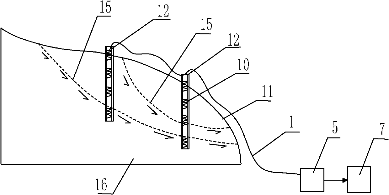
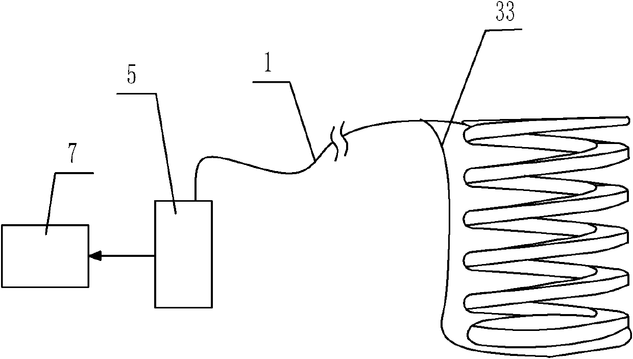
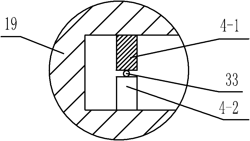
[0043] like figure 1 , 2 A kind of landslide deep displacement monitoring device shown in and 3 comprises the inclinometer tube 12 that is inserted on the landslide 11 and the end passes through the potential sliding surface 15 and extends to the borehole below the bedrock surface 16, the inclinometer tube 12 is provided with a curved test channel for the signal optical fiber-33 to pass through. The curved test channel includes a curved bracket 10 and a plurality of deformed teeth-4-1 that are continuously arranged on the upper and lower opposite sides of the curved bracket 10. and a plurality of deformed teeth two 4-2, the deformed teeth one 4-1 and the deformed teeth two 4-2 are alternately arranged correspondingly, the heads of the deformed teeth one 4-1 and the deformed teeth two 4-2 A curved channel 1 is formed between them, the signal optical fiber 1 33 is passed through the inside of the curved channel 1, and at least one row of the plurality of deformed teeth 4-1 and ...

Embodiment 2

[0049] like Figure 4 As shown, the difference between this embodiment and Embodiment 1 is that the curved support 10 is a spring 38, and a plurality of deformed teeth 4-1 and a plurality of deformed teeth 4-2 are correspondingly arranged in two adjacent springs 38. Between the coil spring wires, the first deformed tooth 4-1 and the second deformed tooth 4-2 are arranged alternately. In this embodiment, the structures, connections and working principles of other parts are the same as those in Embodiment 1.

Embodiment 3

[0051] like Figure 5 and 6 As shown, the difference between this embodiment and Embodiment 1 is that the curved bracket 10 is a corrugated tube 40, and the first deformed tooth 4-1 and the second deformed tooth 4-2 are arranged on the wall 42 of the corrugated tube 40. On the two opposite side surfaces of the recess, the first deformed tooth 4-1 and the second deformed tooth 4-2 are alternately arranged. In this embodiment, the structures, connections and working principles of other parts are the same as those in Embodiment 1.


PUM


Abstract

The invention discloses a landslide depth displacement monitoring device, which comprises an inclinometer pipe, wherein the inclinometer pipe is inserted on a landslide, and the end part of the inclinometer pipe passes through a potential sliding surface and extends into a drill hole below a bedrock surface; a curved test channel for a signal optical fiber I to pass through is arranged in the inclinometer pipe; the curved test channel comprises a curved support, a plurality of deformation teeth I and a plurality of deformation teeth II which are continuously arranged at the upper side and lower side which are opposite in the curved support; the deformation teeth I and the deformation teeth II are correspondingly arranged in a staggered way; the signal optical fiber I is arranged at the inner part of the curved channel in a penetrating way; at least one row of the corresponding deformation teeth of the deformation teeth I and the deformation teeth II share the same height, pitch and bending curvature of the top part contacted with the signal optical fiber I; the joint of the signal optical fiber I is connected with one end of an optical cable; the other end of the optical cable is led to a monitoring station and is connected with a testing unit; and the testing unit is further connected with an upper processing unit. The landslide depth displacement monitoring device can effectively realize remote monitoring of the landslide depth displacement change.

Description

technical field [0001] The invention belongs to the field of sensing technology, and in particular relates to a displacement monitoring device for deep parts of landslides based on optical fiber sensing technology. Background technique [0002] Landslide refers to the phenomenon that the soil and rock mass on the slope slides down the slope in whole or in part along a certain weak surface or weak zone under the action of gravity due to the influence of various factors. Landslide disaster is one of the most dangerous geological disasters. Due to the difference in geological conditions, there are many types and phenomena of landslides, which also creates a relatively high difficulty for the monitoring of landslides. The monitoring indicators of landslides include geological macroscopic trace monitoring indicators, ground displacement monitoring indicators, deep displacement monitoring indicators, inducing factors monitoring indicators, groundwater dynamic monitoring indicator...

Claims


Application Information

Patent Timeline
Patent Type & Authority Applications(China)
IPC IPC(8): G01B11/02G01D5/353
Inventor 杜兵
Owner XIAN JINHE OPTICAL TECH
Why Eureka
Try Eureka