
Safety belt hanger
A safety belt and safety belt lock technology, which is applied in the direction of safety belts and life-saving equipment, can solve the problems that it is not convenient for high-altitude workers to mount safety belts, and achieve the effect of stable fixing method and simple structure
Patent Information
- Authority / Receiving Office
- CN · China
- Patent Type
- Applications(China)
- Current Assignee / Owner
- Publication Date
- 2012-07-18
Smart Images
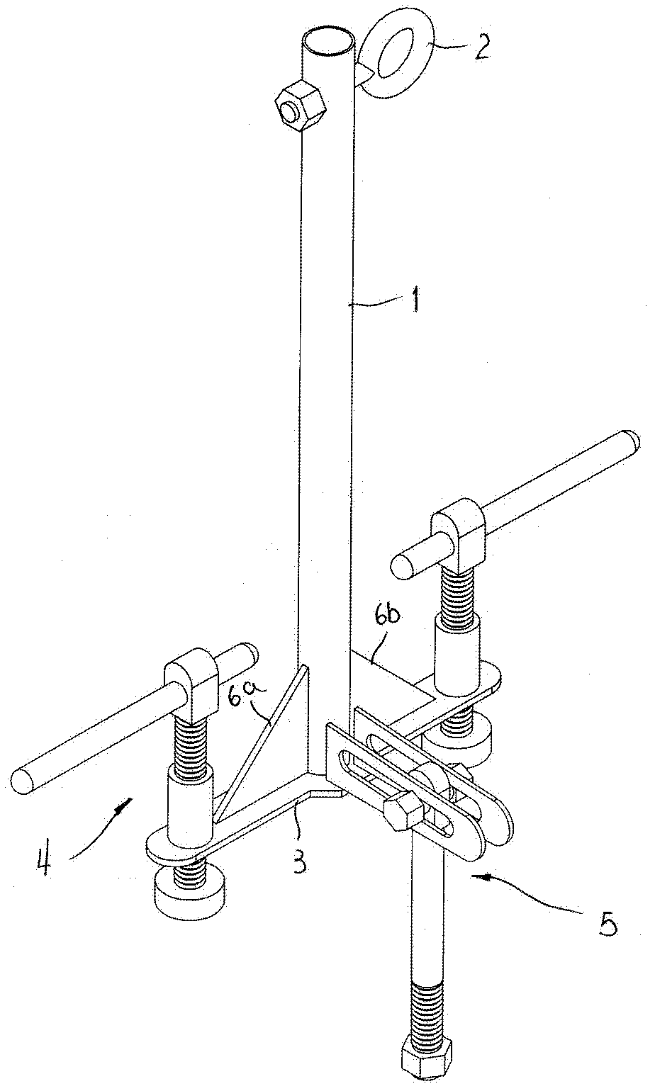
Figure 1 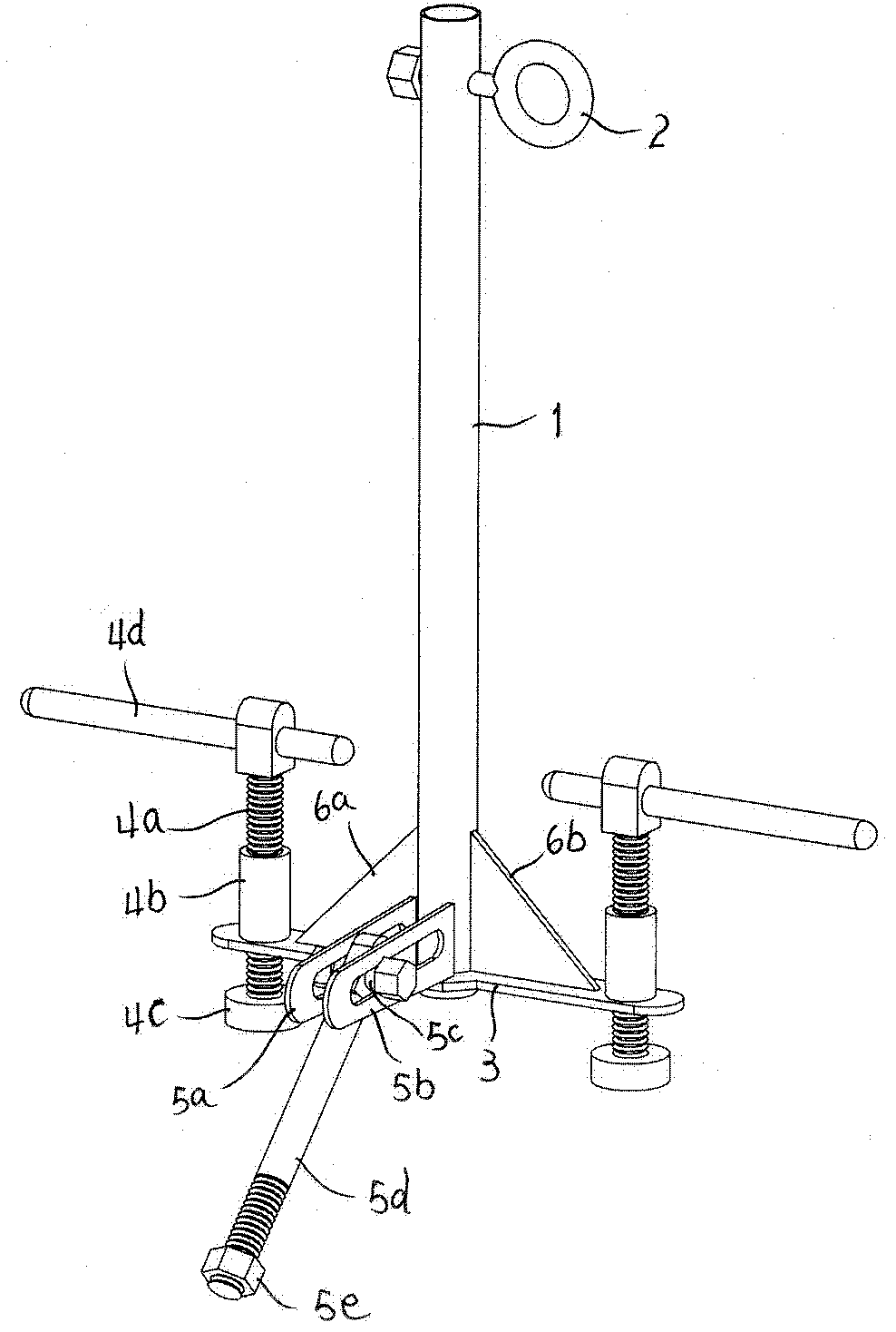
Figure 2 
Figure 3
Abstract
Description
technical field
[0001] The invention relates to electric power construction equipment, in particular to a safety belt connection support frame for hanging safety belts and being convenient to be fixed on power equipment racks. Background technique
[0002] Power equipment such as power transmission towers and power transmission poles are equipped with places such as hanging rings for the safety belt buckle to be articulated, which is not convenient for high-altitude workers to articulate safety belts. According to Article 15.1.8 of the "State Grid Corporation Electricity Safety Work Regulations (Transformation Part)", when performing high-altitude operations, the maintenance personnel must fasten their safety belts, and use the high-hanging and low-use method. It is strictly forbidden to hang on isolating switches, CVT insulators, busbar post insulators and other equipment to prevent equipment from suddenly breaking and causing injury to maintenance personnel. Contents of ...
Examples
Embodiment Construction
[0011] figure 1 , figure 2 As shown, the safety belt hanger is composed of three parts: an insulating rod, an insulating base (including two pressing mechanisms and a pull-back mechanism on the insulating base), and an upper hanging ring. The upper part of the insulating rod 1 is fixed with a hanging ring 2 for seat belt buckle; the lower part of the insulating rod is fixed with an insulating base 3, and the left and right sides of the insulating base 3 are respectively provided with a pressing mechanism 4: the internal thread sleeve 4b is fixed On the insulating base, the screw rod 4a is screwed on the internally threaded sleeve from top to bottom and extends to the bottom of the insulating base, and a top pressure block 4c is fixedly connected to the bottom end of the screw rod, and a handle 4d is inserted in the hole on the upper part of the screw rod ; The front part of the insulating base 3 is provided with a pull-back mechanism 5: two ear plates 5a, 5b are fixed on the...