Multilateral positioning system based on distributed clock

A multilateral positioning and distributed technology, applied in the field of positioning systems, can solve the problems of small coverage, low data update rate, and low positioning accuracy, and achieve the effects of low construction and use costs, high data update rate, and high positioning accuracy

Inactive Publication Date: 2012-07-18
CHINA ELECTRONIC TECH GRP CORP NO 38 RES INST
View PDF4 Cites 6 Cited by
  • Summary
  • Abstract
  • Description
  • Claims
  • Application Information

AI Technical Summary

Problems solved by technology

PSR detects targets by actively emitting electromagnetic waves and receiving detection echoes. It can only obtain target distance and azimuth information, has no aircraft identification capability, small coverage, high construction and operation maintenance costs, and ground station construction is limited by terrain; SSR applies aircraft response The response signal transmitted by the PSR can obtain more monitoring target information than the PSR, but the construction and operation and maintenance costs are also high, the data update rate is low, and the ground station construction is also limited by the terrain
These traditional air traffic control radar surveillance systems generally have the disadvantages of high cost, low positioning accuracy, and difficulty in erection. Therefore, it is urgent to find a new type of air traffic control surveillance system with low cost, high positioning accuracy, and easy erection to adapt to my country's air transport. rapid development of the industry

Method used


Image

  • Multilateral positioning system based on distributed clock
  • Multilateral positioning system based on distributed clock
  • Multilateral positioning system based on distributed clock

Examples


Embodiment Construction

[0017] The content of the present invention will be described below in conjunction with specific embodiments.

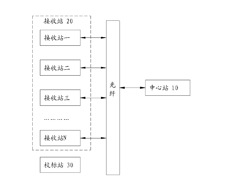
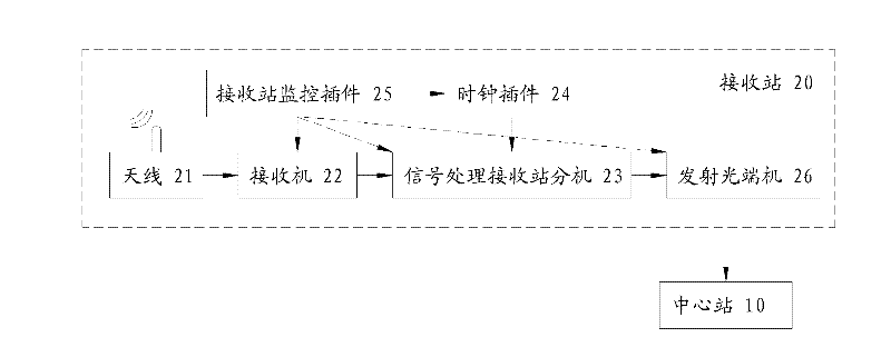
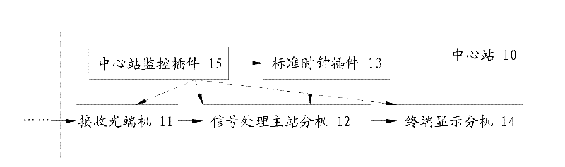
[0018] Such as figure 1 As shown, it is a schematic structural diagram of the distributed clock-based multilateral positioning system of the present invention. The positioning system of the present invention includes: a central station 10 and at least four receiving stations 20 . The central station 10 and each receiving station 20 have a high-precision clock reference with an atomic clock as the core. The receiving stations 20 are distributed in different positions on the target site, and each receiving station 20 is independent of each other, and each receiving station 20 has a sensor for receiving the response signal sent by the civil aviation aircraft or the airport vehicle and recording the arrival time. The receiving station 20 performs data communication with the central station 10 through an optical fiber link, and the central station 10 calculates the prec...


PUM


Abstract

The invention relates to a multilateral positioning system based on a distributed clock. The multilateral positioning system comprises one central station and at least four receiving stations; the central station and each receiving station respectively have a clock reference using an atomic clock as a core; the central station calculates the accurate position of a positioned target according to the signal arrival time difference of different receiving stations; the receiving stations are distributed at different positions on a target field; the receiving stations are mutually independent; furthermore, each receiving station is provided with a sensor used for receiving an answer signal given out by the target and recording an arrival moment; and the receiving stations carry out data communication with the central station through an optical fiber link. The multilateral positioning system provided by the invention adopts an advanced time difference positioning technique; the sense positioning precision of the multilateral positioning system is superior to 1 m; the three-dimensional positioning precision is superior to 5 m; and the sense monitoring requirements of large and medium complicated airports are met. The system is lower in construction cost and use cost, high in positioning precision and high in date replacement rate, is easy to erect, and can be widely used in the field of air traffic management and surveillance.

Description

technical field [0001] The present invention relates to a positioning system, specifically a distributed multilateral positioning system based on atomic clock synchronization technology, and further relates to a multilateral positioning system for an airport to a space vehicle. Background technique [0002] At present, the radar surveillance equipment of the airport air traffic control system mainly includes PSR (Primary Surveillance Radar, primary surveillance radar), SSR (Secondary Surveillance Radar, secondary surveillance radar) and so on. PSR detects targets by actively emitting electromagnetic waves and receiving detection echoes. It can only obtain target distance and azimuth information, has no aircraft identification capability, small coverage, high construction and operation maintenance costs, and ground station construction is limited by terrain; SSR applies aircraft response The response signal transmitted by the PSR can obtain more monitoring target information ...

Claims


Application Information

Patent Timeline
Patent Type & Authority Applications(China)
IPC IPC(8): G01S5/00
Inventor 赵洪立左斌付庆霞徐庆
Owner CHINA ELECTRONIC TECH GRP CORP NO 38 RES INST
Why Eureka
Try Eureka