
Series-connection current limiting circuit of miner lamp intrinsic safety power supply
An intrinsically safe, current-limiting circuit technology, which is applied in the direction of electric lamp circuit layout, electric light source, light source, etc., can solve the problems of large size of miner's lamp, high cost of battery, and large fault current of the circuit
- Summary
- Abstract
- Description
- Claims
- Application Information
AI Technical Summary
Problems solved by technology
Method used
Image

Examples
Embodiment Construction
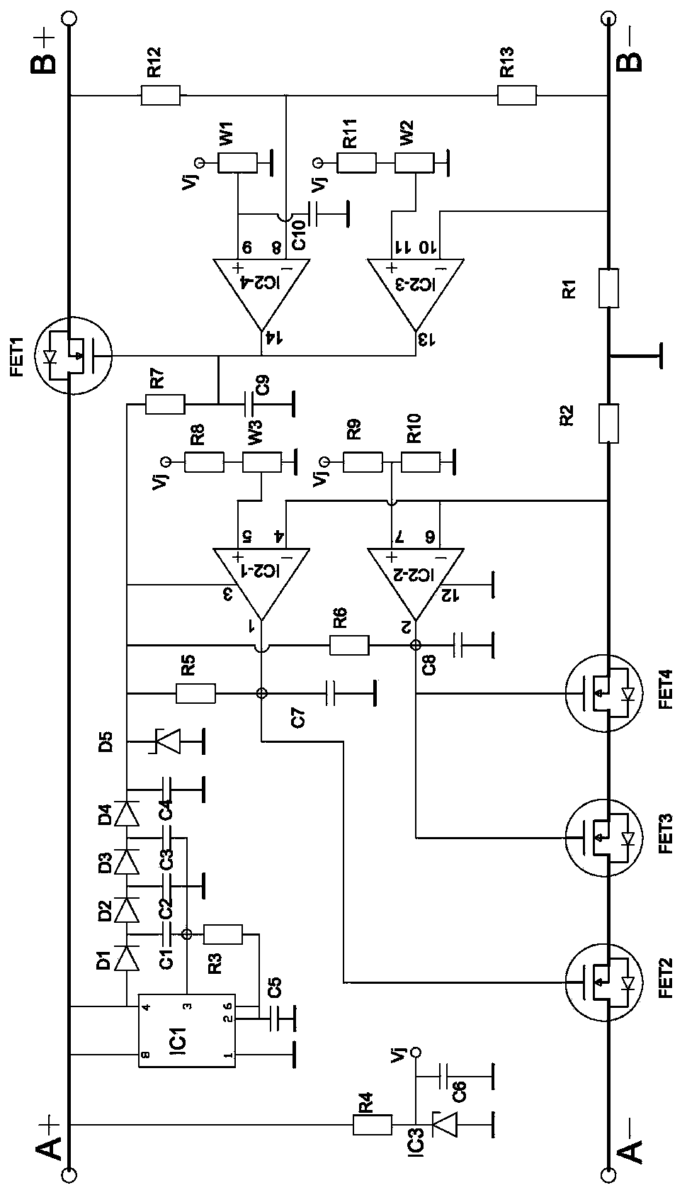
[0016] The circuit of the present invention is composed of power field effect transistors FET1, FET2, FET3, FET4, integrated circuits IC1, IC2, IC3 and resistance-capacitance elements.
[0017] The integrated circuit IC1 is a 555 time base circuit, packaged with 8 pins, 1 pin is grounded, 2 pins and 6 pins are connected to capacitor C5 and resistor R3, 3 pins are connected to the other end of capacitors C1, C3 and R3, 4 pins, After the 8-pin is connected, it is connected to the external power supply A+, and the 5-pin is vacant.
[0018] The integrated circuit IC2 is a 339 four-voltage comparator, packaged with 14 pins, its 1 pin is connected to the control pole of the field effect transistor FET2, the 2 pins are respectively connected to the control poles of the field effect transistor FET3 and FET4, the 3 pin is connected to the positive pole of the working power supply, and 4 Pin and pin 6 are connected to the current sampling resistor R2, pin 5 and pin 7 are respectively co...
PUM
 Abstract
Description
Claims
Application Information