Stamping die

A stamping die, convex and concave die technology, applied in the direction of forming tools, manufacturing tools, metal processing equipment, etc., can solve the problems of complex stamping die structure, complex processing technology, difficult workpiece ejection, etc., so as to save the unloading ejector device , Simplify the overall structure and reduce the difficulty

Active Publication Date: 2012-10-24
DATONG ELECTRIC LOCOMOTIVE OF NCR
View PDF5 Cites 19 Cited by
  • Summary
  • Abstract
  • Description
  • Claims
  • Application Information

AI Technical Summary

Problems solved by technology

[0004] During the research process of the present invention, the inventor found that the stamping dies of the above-mentioned prior art have the following technical defects: the existing stamping dies usually have independent guiding devices and unloading devices, thus resulting in complex structures of the stamping dies and difficult processing.

Method used


Image

  • Stamping die
  • Stamping die
  • Stamping die

Examples


Embodiment Construction

[0030] In order to make the purpose, technical solutions and advantages of the present invention clearer, the technical solutions in the embodiments of the present invention will be clearly and completely described below in conjunction with the accompanying drawings in the embodiments of the present invention. Obviously, the described embodiments are the Some, but not all, embodiments are invented. Based on the embodiments of the present invention, all other embodiments obtained by persons of ordinary skill in the art without creative efforts fall within the protection scope of the present invention.

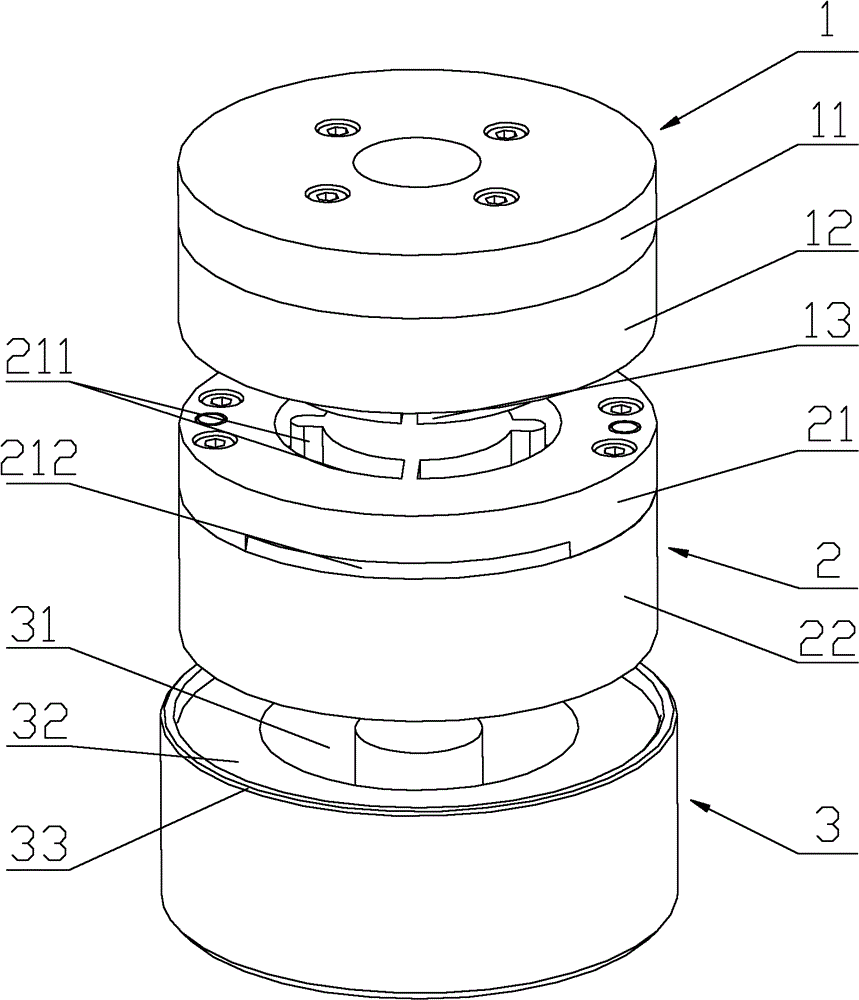
[0031] refer to figure 1 , figure 1 A schematic diagram of a three-dimensional structure of a stamping die provided by an embodiment of the present invention.

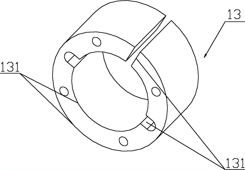
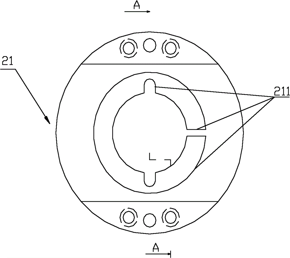
[0032] First of all, it should be explained that the overall shape of the stamping die provided in this embodiment is a cylindrical structure, and the shape of each component is also a cylindrical or circular plate str...


PUM


Abstract

The invention discloses a stamping die which comprises an upper die, a lower die and a supporting seat, wherein the upper die comprises an upper punch-die; the lower die comprises a lower punch-die; the upper punch-die is matched with the lower punch-die; the lower die is arranged on the supporting seat; the lower die further comprises a guide device; and the guide device is arranged at the upper end face of the lower punch-die and provided with a guide part which is matched with the upper punch-die so as to enable the upper punch-die to slide in the guide part. The stamping die provided by the invention comprises the upper die, the lower die and the supporting seat, wherein the lower die is provided with the guide device; and the guide part of the guide device is matched with the upper punch-die of the upper die. Since the guide device is simple in structure, compared with the prior art, the stamping die has the advantages that a guide post structure and a guide sleeve structure are omitted, the overall structure of the stamping die is simplified, the difficulty of the processing process is reduced, and the production cost is lowered.

Description

technical field [0001] The invention relates to sheet material processing technology, in particular to a stamping die. Background technique [0002] Stamping dies are dies used for sheet metal stamping and blanking separation, including punching dies, bending dies, deep drawing dies, and hole turning dies. In the stamping die, the sheet is formed through the mold cavity, and the sheet is separated or cut through the punching edge of the stamping die. The most commonly used stamping die has only one station to complete a production process. In order to improve productivity, multiple stamping processes, such as blanking, deep drawing, punching, trimming and other processes, can be designed on one stamping die, so that the sheet can complete multiple stamping processes at one station. The mold is called a compound mold. [0003] Stamping dies usually include upper die, lower die, upper die fixing plate, lower die fixing plate, guiding device, positioning device and unloading...

Claims


Application Information

Patent Timeline
IPC IPC(8): B21D37/10B21D37/12
Inventor 管玉成梁家红
Owner DATONG ELECTRIC LOCOMOTIVE OF NCR
Why Eureka
Try Eureka