
Enhanced vapor injection device of air energy heat pump, control method and water heater for air energy heat pump
An air energy heat pump and air injection enthalpy increasing technology, which is applied in heat pumps, fluid heaters, refrigerators, etc., can solve the problems of high cost of air energy heat pump systems, high price of air injection enthalpy increasing compressors, and complicated pipeline connections, etc., to achieve improved Energy efficiency, reduced suction and exhaust pressure difference, and cost reduction effects
- Summary
- Abstract
- Description
- Claims
- Application Information
AI Technical Summary
Problems solved by technology
Method used
Image

Examples
Embodiment 1
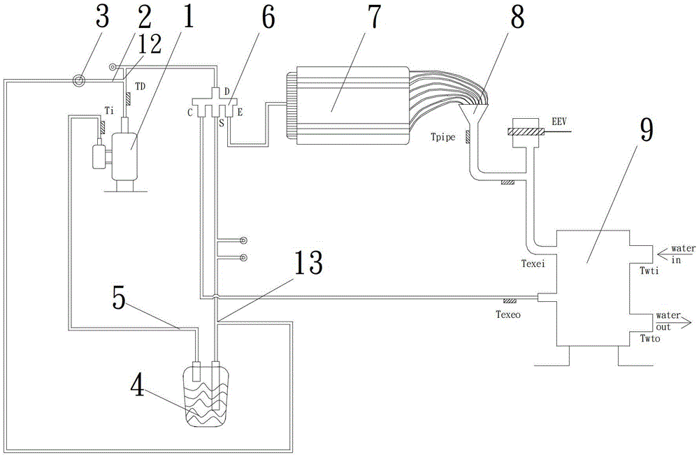
[0026] Such as figure 1 As shown, the air energy heat pump air injection enthalpy increasing device includes a compressor 1, an intake pipe 2, a first bypass valve 3, a liquid reservoir 4, and a return air pipe 5; The exhaust port is connected, and the end is connected with the inlet of the liquid reservoir 4; the front end of the return air pipeline 5 is connected with the outlet of the liquid reservoir 4, and the end is connected with the suction port of the compressor 1; the first bypass valve 3 is set at the inlet Pipeline 2 front end. The above-mentioned parts constitute the air injection enthalpy increasing circulation loop.
[0027] continue to see figure 1 , The heat exchange cycle circuit of the air energy heat pump water heater includes a compressor 1, a four-way valve 6, a condenser 7, a liquid separator 8, a water heat exchanger 9, and a liquid reservoir 4, and the above-mentioned parts are connected in sequence through copper pipes.
[0028] continue to see fi...
Embodiment 2
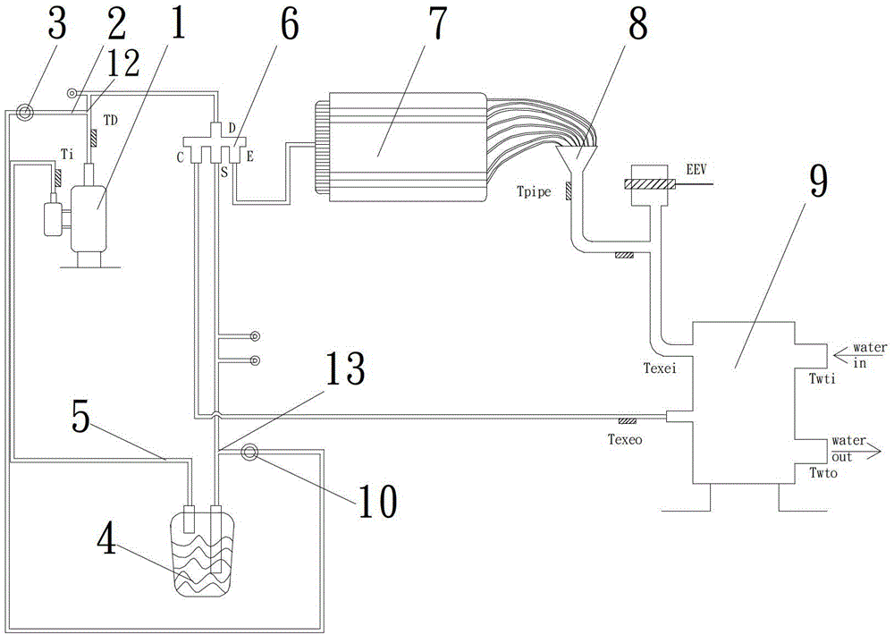
[0037] Such as figure 2 As shown, the air energy heat pump air injection enthalpy increasing device includes a compressor 1, an intake pipe 2, a first bypass valve 3, a second bypass valve 10, a pressure reducing valve (not shown in the figure), a liquid reservoir 4, The air return pipeline 5; wherein, the front end of the air intake pipeline 2 is connected with the exhaust port of the compressor 1, and the end is connected with the inlet of the liquid reservoir 4; the front end of the air return pipe 5 is connected with the outlet of the liquid reservoir 4, and the end is connected with the compressor The suction port of the machine 1 is connected; the first bypass valve 3 is arranged at the front end of the intake pipe 2, and the second bypass valve 10 and the pressure reducing valve are arranged at the end of the return air pipe 5. The above-mentioned parts constitute the air injection enthalpy increasing circulation loop.
[0038] continue to see figure 2 , The heat ex...
Embodiment 3
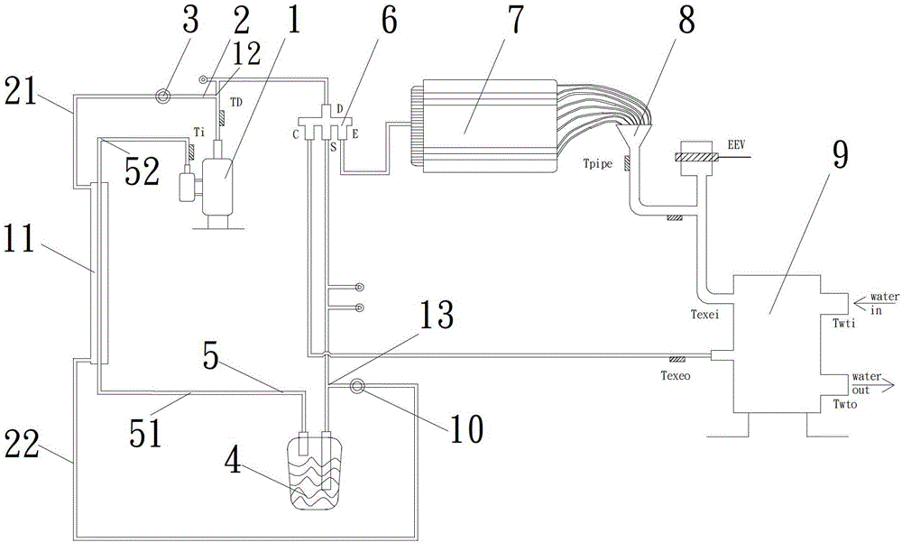
[0048] Such as image 3 As shown, the air energy heat pump air injection enthalpy increasing device includes a compressor 1, an intake pipe 2, a first bypass valve 3, an air injection enthalpy increasing preheater 11, a second bypass valve 10 and a pressure reducing valve (not shown in the figure Out), liquid storage 4, return air pipeline 5; wherein, the front end of the intake pipe 2 is connected with the exhaust port of the compressor 1, and the end is connected with the inlet of the liquid storage 4; the front end of the return air pipeline 5 is connected with the liquid storage The outlet of 4 is connected, and the end is connected with the suction port of compressor 1; the first bypass valve 3 is arranged at the front end of the intake pipe 2, the second bypass valve 10 and the pressure reducing valve are arranged at the end of the return air pipe 5, and the air injection The enthalpy preheater 11 is connected in series with the middle part of the intake pipe 2 and the r...
PUM
 Abstract
Description
Claims
Application Information