

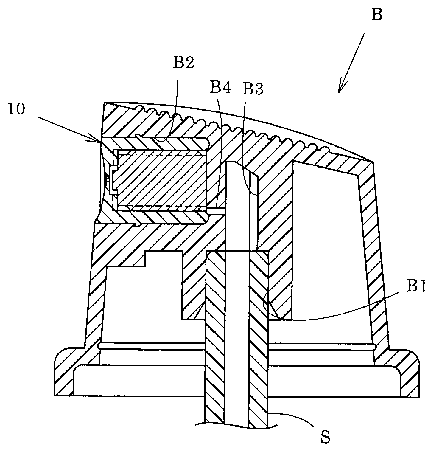
Nozzle hole mechanism
A nozzle and rotary chamber technology, which is applied in the direction of injection device, injection device, liquid injection device, etc., can solve the problems of reduced flow velocity, large resistance, and turbulent flow of the content, and achieves less spray volume, increased rotational speed, and small nozzle diameter. Effect
- Summary
- Abstract
- Description
- Claims
- Application Information
AI Technical Summary
Problems solved by technology
Method used
Image

Examples
Embodiment 1
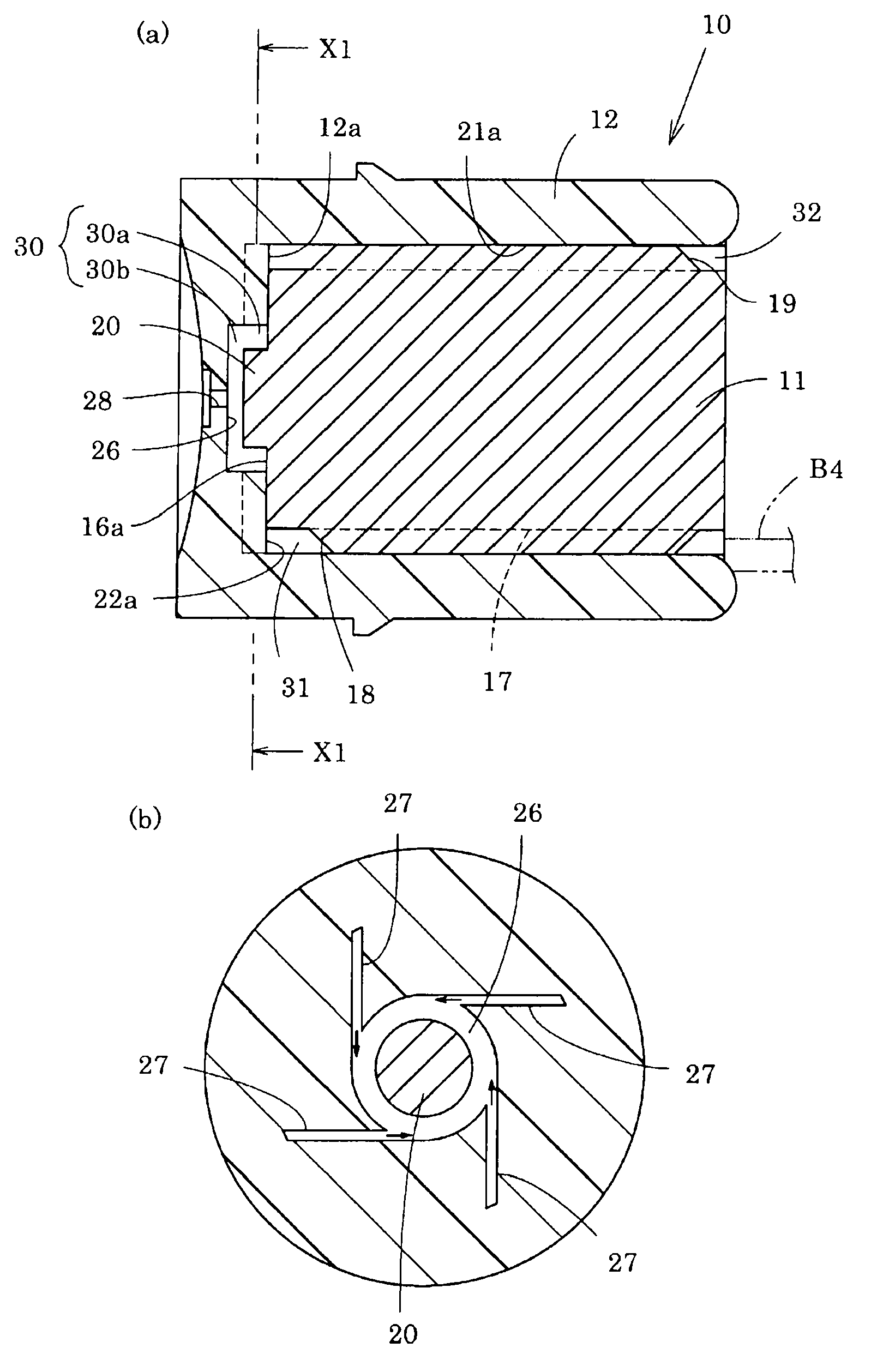
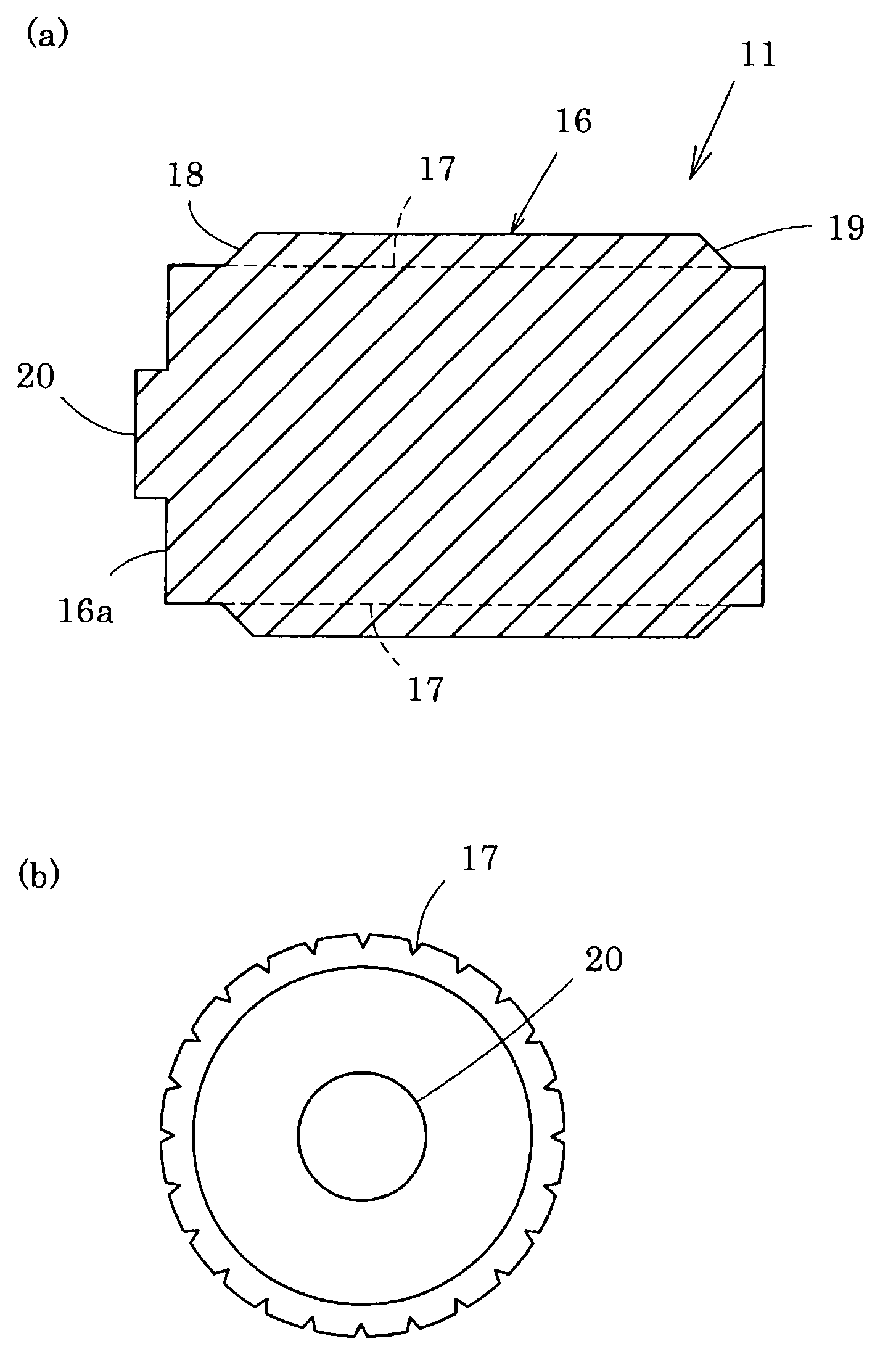
[0068] Protruding portion 20 of core 11: outer diameter 1.5 mm, height 0.2 mm
[0069] Recess 26 of nozzle member 12: inner diameter 2.0 mm, height 0.4 mm, nozzle diameter 0.15 mm
[0070] Passage (groove 27): width 0.15mm, depth 0.2mm, 4 (passage area: 0.12mm 2 )
[0071] In this spout mechanism 10, the outer diameter of the protruding portion 20 is 75% of the inner diameter of the recessed portion 26, the height of the protruding portion 20 is 50% of the height of the recessed portion 26, and the area ratio of the passage to the spout is 6.8.
Embodiment 2
[0073] Protruding portion 20 of core 11: outer diameter 1.5 mm, height 0.05 mm
[0074] Recess 26 of nozzle member 12: inner diameter 2.0 mm, height 0.4 mm, nozzle diameter 0.15 mm
[0075] Passage (groove 27): width 0.15mm, depth 0.2mm, 4 (passage area: 0.12mm 2 )
[0076] In this spout mechanism 10, the outer diameter of the protruding portion 20 is 75% of the inner diameter of the recessed portion 26, the height of the protruding portion 20 is 15% of the height of the recessed portion 26, and the area ratio of the passage to the spout is 6.8.
Embodiment 3
[0078] Protrusion 20 of core 11: inner diameter 0.75mm, height 0.2mm
[0079] Recess 26 of nozzle member 12: inner diameter 2.0 mm, height 0.4 mm, nozzle diameter 0.15 mm
[0080] Passage (groove 27): width 0.15mm, depth 0.2mm, 4 (passage area: 0.12mm 2 )
[0081] In this spout mechanism 10, the outer diameter of the protruding portion 20 is 37.5% of the inner diameter of the recessed portion 26, the height of the protruding portion 20 is 50% of the height of the recessed portion 26, and the area ratio of the passage to the spout is 6.8.
PUM
| Property | Measurement | Unit |
|---|---|---|
| Diameter | aaaaa | aaaaa |
| Length | aaaaa | aaaaa |
| Outer diameter | aaaaa | aaaaa |
Abstract
Description
Claims
Application Information