Microwave photocatalytic coupling type waste water degrading device with reinforced catalyst interception procedure

A waste water degradation device and catalyst technology, applied in the direction of light water/sewage treatment, chemical instruments and methods, water/sewage multi-stage treatment, etc., can solve problems such as consumption

Inactive Publication Date: 2013-06-12
NINGBO UNIV
View PDF4 Cites 3 Cited by
  • Summary
  • Abstract
  • Description
  • Claims
  • Application Information

AI Technical Summary

Problems solved by technology

[0029] The CN102260003A scheme pumps air into the quartz tube containing the electrodeless ultraviolet lamp to achieve the purpose of ventilation, cooling and cooling of the electrodeless ultraviolet lamp, and the air flowing through the quartz tube will be partially transformed due to the irradiation of ultraviolet rays. Therefore, the air flowing out of the quartz tube is of course air containing some ozone. This scheme transmits the ozone-containing air to the microporous aeration head located below the reactor, and releases it from the microporous aeration head. During the bottom-up rise of these ozone-containing bubbles, the ozone contained in it will encounter the organic molecules encountered in the journey and undergo a redox reaction. Of course, this redox reaction will consume part of the ozone. There is no doubt about it. However, as mentioned above, as the scheme shown in CN102260003A, many factors that cannot be ignored inevitably limit its reactor size and limit its actual processing capacity, as clearly shown in its specific examples As indicated, it can only be a small reactor with a single treatment capacity of only about 40 liters in a single tank. In the case of such a small reactor and a small inner cavity, because the overall size itself is very small, then its reaction The longitudinal size of the inner cavity of the device or the depth of filling the liquid can only be a very small size. As clearly shown in its specific implementation, this size is only about 40 centimeters, and the depth of filling the liquid is only ab

Method used


Image

  • Microwave photocatalytic coupling type waste water degrading device with reinforced catalyst interception procedure

Examples


Embodiment Construction

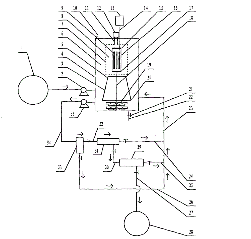
[0073] exist figure 1 In the shown embodiment of the present case, the structure of the device includes a reactor 4, which is a hollow container, and the outline of the reactor 4 is in the shape of a cube, a cuboid, a cylinder, an ellipse, or a polygonal prism. Body shape, spherical shape or ellipsoidal shape, many microporous aeration heads 19 are installed at the bottom position of this reactor 4 inner cavity, and, quartz tube 16, this quartz tube 16 is erected in the inside of described reactor 4 cavity position, the two ends of the quartz tube 16 are equipped with plugging caps 15, 17, and the two plugging caps 15, 17 respectively located at the two ends of the quartz tube 16 are provided with ventilation ports, and the electrodeless ultraviolet lamp 9 , the electrodeless ultraviolet lamp 9 is rod-shaped, ring-shaped, spherical, starfish-shaped or sea urchin-shaped, the number of the electrodeless ultraviolet lamp 9 is at least one, and the electrodeless ultraviolet lamp 9...


PUM


Abstract

The invention relates to a microwave photocatalytic coupling type waste water degrading device with a reinforced catalyst interception procedure and belongs to the technical field of waste water treatment. The existing microwave photocatalytic degradation technology of industrial waste water containing organic pollutants has such problems as weak catalyst interception procedure, small single-tank waste water treatment capacity of reactor and insufficient general circulation strength of internal liquid, and the like, and the scheme is used for integrally solving the problems under the condition of taking the coupling action into account. In the scheme, a metal cage is spanned near the periphery of a quartz tube provided with an electrodeless ultraviolet lamp in the reactor to constrain the microwave in a limited space, so as to greatly expand the design volume of a non-microwave irradiation space to greatly improve the single-tank treatment capacity; a horn-shaped member used for reinforcing liquid circulation is spanned right below the metal cage; an external cascaded three-level back wash filter is used for precisely intercepting catalyst particles; and the material selection of the filter element is not limited.

Description

technical field [0001] The invention relates to a microwave photocatalytic coupled wastewater degradation device with enhanced catalyst retention link, belonging to the technical field of CO2F wastewater treatment. Background technique [0002] Microwave photocatalytic degradation treatment technology, as an effective harmless treatment technology for industrial wastewater containing organic pollutants, has attracted much attention in recent years. [0003] Regarding the microwave photocatalytic degradation technology, as an example, refer to the Chinese patent application with publication number CN102260003A. [0004] The Chinese patent application with the publication number CN102260003A uses microwaves as the excitation source to excite the electrodeless ultraviolet lamp to emit ultraviolet rays, and irradiates the suspension mixed with photocatalyst titanium dioxide particles inside the liquid. The electrodeless ultraviolet lamp is covered and protected by a quartz tube....

Claims


Application Information

Patent Timeline
IPC IPC(8): C02F9/08C02F1/30
Inventor 李榕生任元龙孙杰葛从辛王冬杰周汉坤干宁孔祖萍
Owner NINGBO UNIV
Why Eureka
Try Eureka