Equipment for conveying assemblies for labeling containers

A technology for labeling and assembling parts, which is applied in the field of equipment for conveying container labeling parts, which can solve problems such as large space, hindrance to independence, and complex structure, and achieve the effects of sensitive speed adjustment, elimination of space consumption, and high torque

Inactive Publication Date: 2015-10-14
KRONES AG
View PDF7 Cites 0 Cited by
  • Summary
  • Abstract
  • Description
  • Claims
  • Application Information

AI Technical Summary

Problems solved by technology

The structure of the device is complex and leads to a large overall height in the direction of the axis of rotation, so that a large amount of assembly space is required above the support structure of the labeling assembly
In addition, the functionality of the device needs to be integrated into the gear drive system, which increases the inconvenience of the construction and prevents the independence of the modular structure of the device from the labeling assembly, among other things also hinders the control of the rotation speed of the hub. independence
One reason in particular is that, for the large overall height of the known devices, due to the central bearing arrangement of the hub which requires a stable structure and due to the independently disconnected overload clutches which take up a large amount of height, in the direction of the axis of rotation Need a lot of space above the hub of the

Method used


Image

  • Equipment for conveying assemblies for labeling containers

Examples


Embodiment Construction

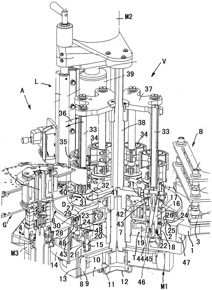
[0019] Although the plant V with the plate-shaped support structure 1 can be a structural unit which can be prefabricated independently and possibly can be integrated into different labeling assemblies A, built onto the plate-shaped (steel plate or light metal alloy plate) support structure 1, For example, in the process of container labeling, the equipment V used to transfer the assembly is in the figure 1 is shown integrated into labeling assembly A. The apparatus V is for conveying individual assemblies, such as label or foil cutters, etc., in a rotational movement about an at least substantially vertical axis of rotation.

[0020] exist figure 1 In the exemplary embodiment shown, further components of the labeling assembly A have been arranged functionally or in a special geometric relationship to each other, for example on the support structure 1 , namely: the assembly box B for the assembly; a gluing unit L for supplying and applying e.g. cold glue to each assembly bei...


PUM


Abstract

The device (V) has a hub (5) centrally coupled to a direct drive (M1) such that the hub is driven by the drive around a rotational axis in a stationary hub bearing arrangement (24) that is arranged in an outer circumferential region of the hub. A set of drive shafts (16) is coupled to transfer shafts (33) carrying transfer elements (34). A lantern wheel (T) is arranged under the hub and comprises drive pinions and toothed wheel segments (19). A stationary control cam plate (14) pivotally rotates the drive shafts, and the drive is arranged under the plate. The hub is arranged under the plate. The direct drive is designed as an electrical torque motor or an electrical servomotor.

Description

technical field [0001] The invention relates to a device for conveying assemblies for labeling containers. Background technique [0002] This device, which can be attached to a labeling assembly and is known from DE 30 44 879 A and DE 32 16 138 A, has a fixed gearbox housing whose bottom forms the cam control of the lantern pinion plate, the gearbox is closed on the upper side between the hub cover and the gearbox housing via a sliding ring seal, since at least the lantern pinion arranged between the hub and the cam control plate is inserted into the oil sump. A fixed shaft is fitted to the center of the cam control plate, with the hub being rotatably centrally supported on said fixed shaft by two axially spaced ball bearings. The hub has a peripheral tooth profile which meshes with the driving gear of the gearbox forming the drive of the device, each drive shaft in the hub has at its lower end a drive pinion fitted for co-rotation and a pivotable lantern The gear segments...

Claims


Application Information

Patent Timeline
Patent Type & Authority Patents(China)
IPC IPC(8): B65C9/10
CPCB65C9/04B65C9/14B65C9/16
Inventor 克里斯蒂安·施托伊贝尔
Owner KRONES AG
Why Eureka
Try Eureka