Pneumatic muscle driving bionic frog bouncing leg mechanism employing dual-joint mechanism form

A pneumatic muscle and double-joint technology, applied in the field of robotics, can solve problems such as poor jumping ability, inflexible movement, and complex structure, and achieve the effects of short contraction stroke, flexible movement, and simplified leg structure

Active Publication Date: 2013-08-14
HARBIN INST OF TECH
View PDF9 Cites 15 Cited by
  • Summary
  • Abstract
  • Description
  • Claims
  • Application Information

AI Technical Summary

Problems solved by technology

[0006] The purpose of the present invention is to solve the problem that the bouncing legs of the existing imitation frog jumping robot have inflexible movement, complex structure and poor bouncing ability, and then provide a pneumatic muscle-driven imitation frog bouncing leg mechanism in the form of a double-joint mechanism

Method used


Image

  • Pneumatic muscle driving bionic frog bouncing leg mechanism employing dual-joint mechanism form
  • Pneumatic muscle driving bionic frog bouncing leg mechanism employing dual-joint mechanism form
  • Pneumatic muscle driving bionic frog bouncing leg mechanism employing dual-joint mechanism form

Examples


specific Embodiment approach 1

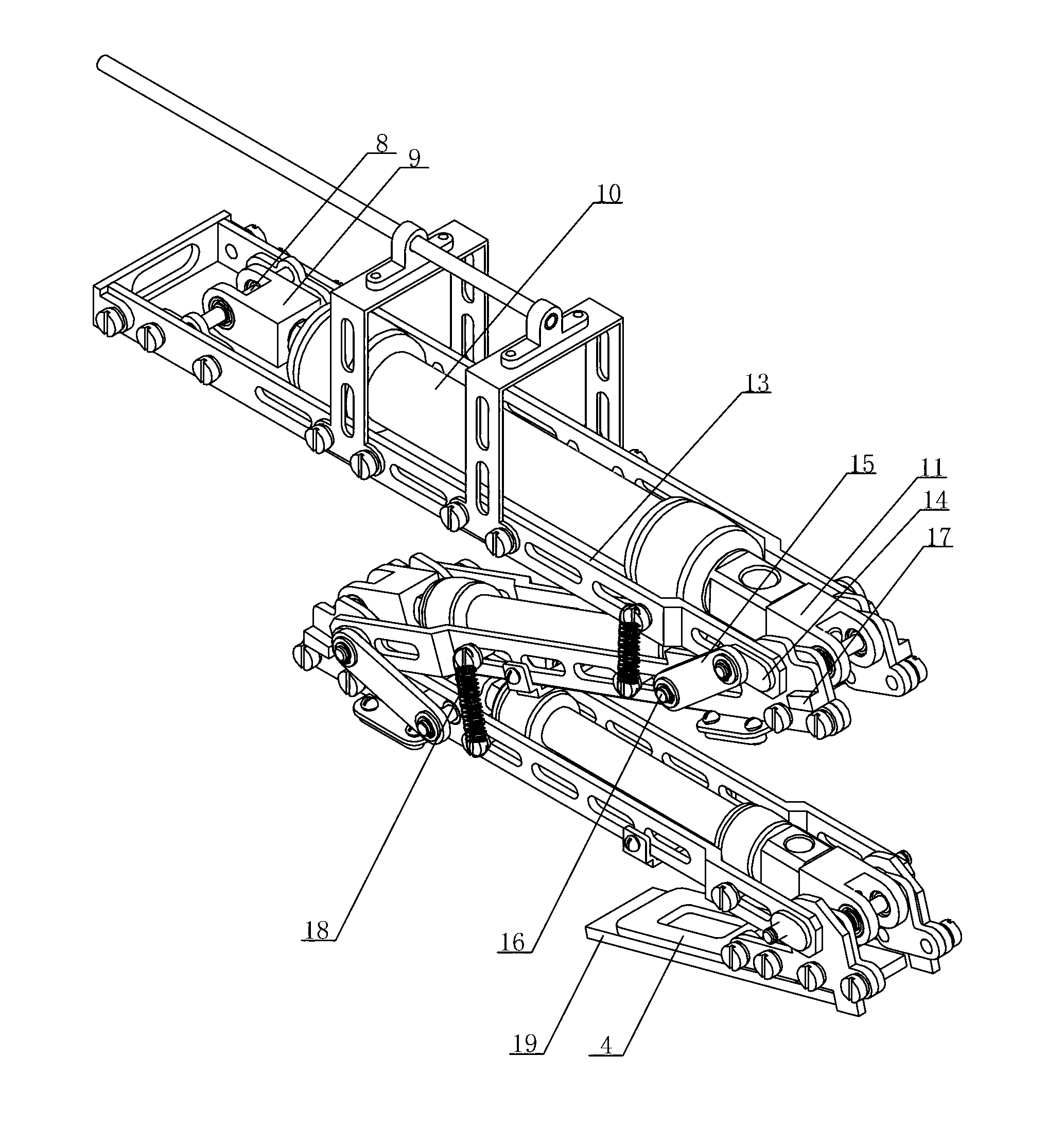
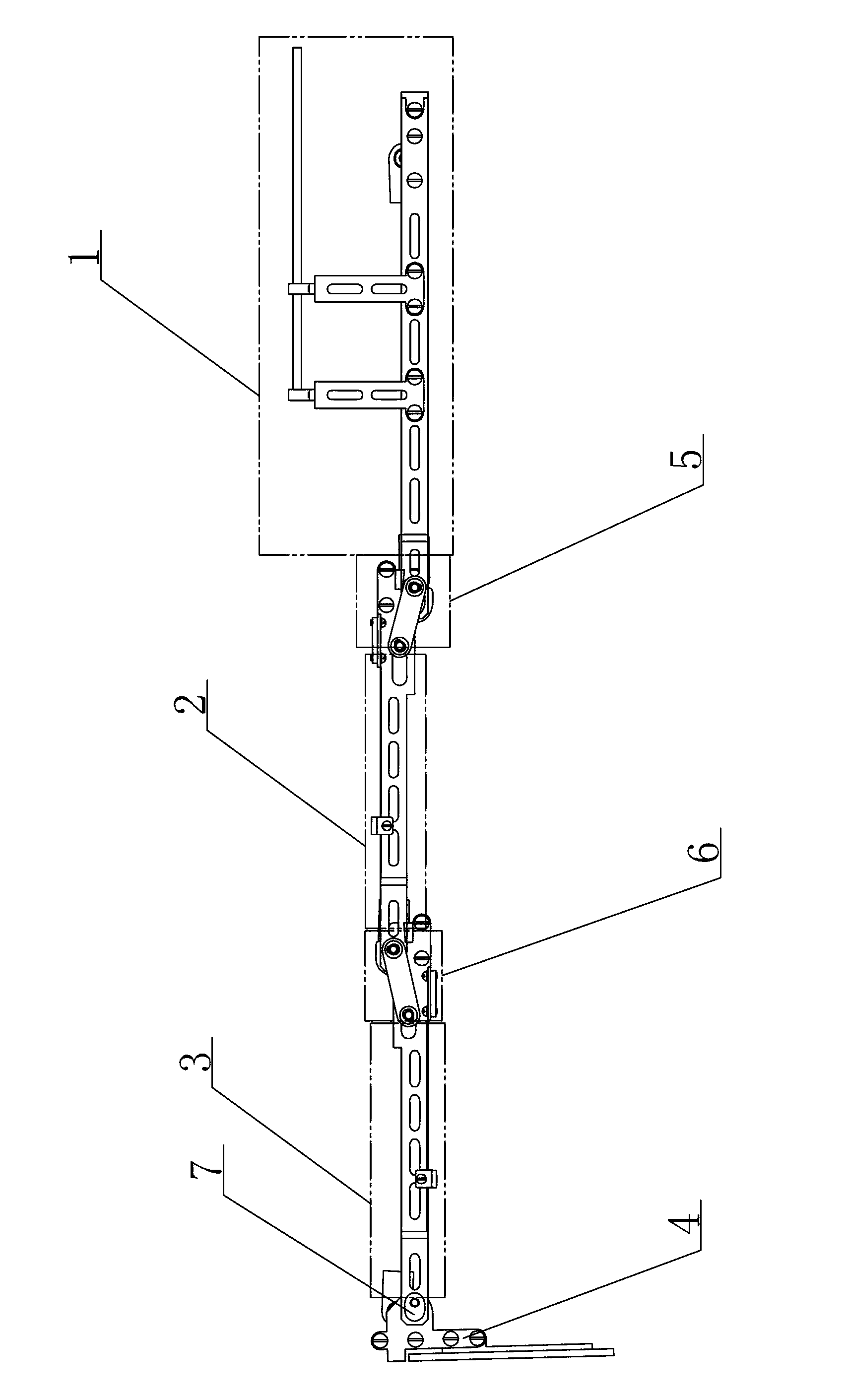
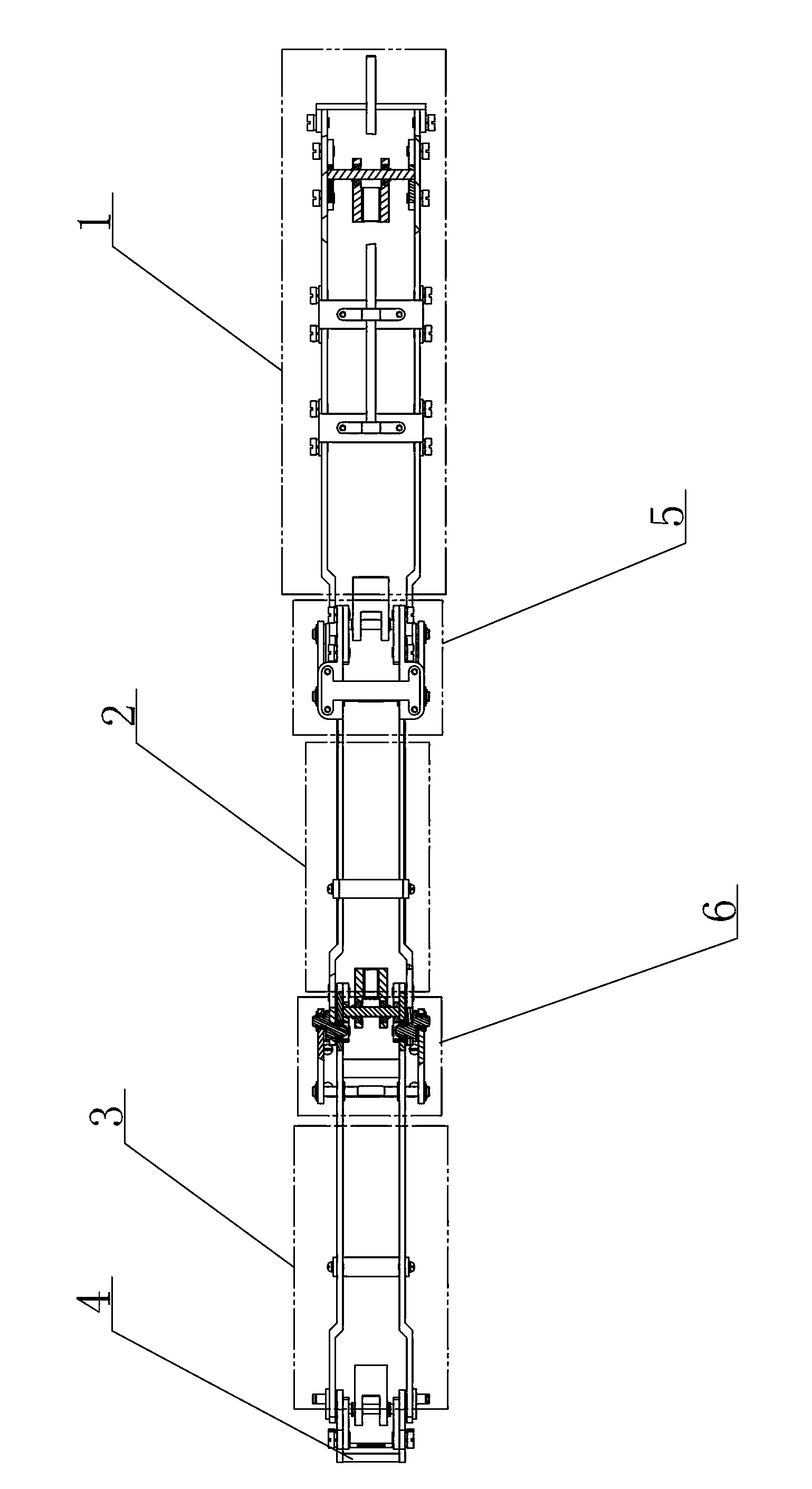
[0015] Specific implementation mode one: combine Figure 1-Figure 3 Describe this embodiment, the pneumatic muscle-driven imitation frog jumping leg mechanism in the form of a double-joint mechanism in this embodiment includes a trunk body 1, a thigh body 2, a calf body 3, a foot 4, a hip joint 5, a knee joint 6 and an ankle joint 7. The trunk body 1, thigh body 2 and calf body 3 all use pneumatic muscles as the drivers for joint extension, and the trunk body 1, thigh body 2, calf body 3 and foot 4 are connected through the hip joint 5 and knee joint respectively. 6 and the ankle joint 7 are rotatably connected, the trunk body 1, the thigh body 2 and the calf body 3 have the same structure, and the hip joint 5 and the knee joint 6 have the same structure.

[0016] The present invention is realized by connecting the muscle force points on the moving limbs of the two joints. Therefore, in addition to the muscle's own contraction, the driving stroke of the muscle also has the ov...

specific Embodiment approach 2

[0018] Specific implementation mode two: combination Figure 1-Figure 3 Describe this embodiment, the torso body 1 of this embodiment includes a first shaft 8, a first connecting member 9, a pneumatic muscle 10, a second connecting member 11, a second shaft 12 and a bracket 13, the first shaft 8 and the second shaft 12 are arranged on both sides of the bracket 13 respectively, and the two ends of the pneumatic muscle 10 are rotatably connected to the first shaft 8 and the second shaft 12 through the first connecting piece 9 and the second connecting piece 11 respectively. So set, the structure is simple. Other compositions and connections are the same as in the first embodiment.

specific Embodiment approach 3

[0019] Specific implementation mode three: combination Figure 1-Figure 3 Describe this embodiment, the length and diameter of the pneumatic muscle 10 of the thigh body 2 and the pneumatic muscle 10 of the calf body 3 of this embodiment are smaller than the length and diameter of the pneumatic muscle 10 of the trunk body 1 . With this setup, the power and retraction travel is greater. Other compositions and connections are the same as those in the second embodiment.


PUM


Abstract

The invention discloses a pneumatic muscle driving bionic frog bouncing leg mechanism employing a dual-joint mechanism form, and relates to a pneumatic muscle driving bionic frog bouncing leg mechanism. The bionic frog bouncing leg mechanism solves the problems that a bouncing leg of the existing bionic frog bouncing robot does not move flexibly, and is complicated in structure and poor in bouncing ability. The bionic frog bouncing leg mechanism is characterized in that a trunk body (1), a thigh body (2) and a crus body (3) adopt pneumatic muscles as drivers for stretching joints; the trunk body (1), the thigh body (2), the crus body (3) and a foot part (4) are rotationally connected by a hip joint (5), a knee joint (6) and an ankle joint (7); structures of the trunk body (1), the thigh body (2) and the crus body (3) are the same; and structures of the hip joint (5) and the knee joint (6) are the same. The bionic frog bouncing leg mechanism is applied to the bouncing robot.

Description

technical field [0001] The invention relates to a pneumatic muscle-driven imitation frog bouncing leg mechanism, in particular to a pneumatic muscle-driven imitative frog bouncing leg mechanism in the form of a double-joint mechanism, which belongs to the field of robots. Background technique [0002] In 1984, since Professor Raibert of the Massachusetts Institute of Technology's Leg Laboratory created a single-leg robot that jumped, many institutions at home and abroad have launched research on bouncing robots. Frogs have slender jumping legs and excellent jumping ability, and they have become the object of research on bionic robots. [0003] The frog-like jumping robot developed by Harbin Institute of Technology uses a five-bar mechanism as a jumping leg, which is driven by a spring. The synchronous gear of the five-bar mechanism limits the leg to only one degree of freedom. The designed robot leg is composed of a DC motor, a jumping leg driver and a jumping leg actuator....

Claims


Application Information

Patent Timeline
Patent Type & Authority Applications(China)
IPC IPC(8): B62D57/02
Inventor 赵杰樊继壮刘玉斌张伟
Owner HARBIN INST OF TECH
Why Eureka
Try Eureka