Power supply control switch

A power control and switching technology, applied in electrical switches, flip/rocker switches, circuits, etc., can solve problems such as large material loss, product performance cannot be guaranteed, LED display lights cannot be placed in active areas, etc., to reduce difficulty, Increase the transmission effect and facilitate the installation

Active Publication Date: 2015-01-21
HUNAN SIASE ELECTRIC INDAL
View PDF6 Cites 0 Cited by
  • Summary
  • Abstract
  • Description
  • Claims
  • Application Information

AI Technical Summary

Problems solved by technology

[0003] In the prior art, the pressure block of the power switch can only move in the center, and the LED display light cannot be placed in the active area of ​​the block under the button
The movement of the springboard is to use the spring to directly contact with the springboard to make the springboard move. Such contact movement will cause large material loss and product performance cannot be guaranteed.

Method used


Image

  • Power supply control switch
  • Power supply control switch
  • Power supply control switch

Examples


Embodiment 1

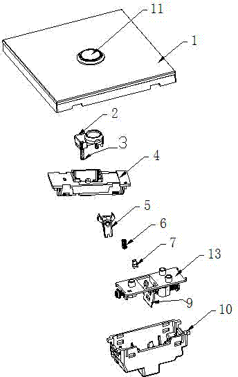
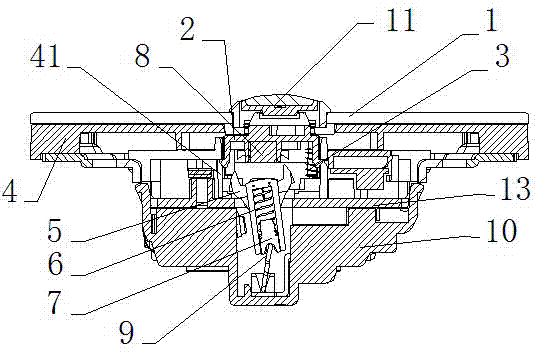
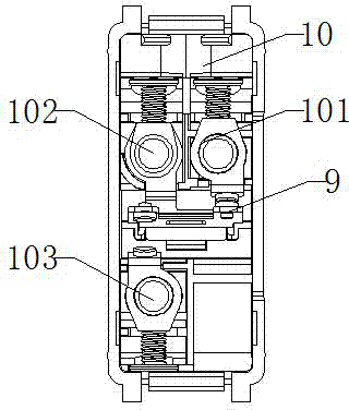
[0055] Such as figure 1 , 2 Shown, a kind of power control switch, it comprises panel 1, switch system, rear seat 10, and above-mentioned panel 1 is provided with the button 11 that transmits external pressure, and above-mentioned switch system is installed on back seat 10 and panel between 1, such as image 3 As shown, the bottom of the above-mentioned rear seat 10 is equipped with conductive side columns I 101, conductive side columns II 102, and conductive brackets 103; the above-mentioned switch system is a self-resetting reciprocating switch structure, which includes the following structural parts:

[0056] Such as Figure 4 As shown, the briquetting block assembly 2 is used as the first part to withstand the external pressing force, and the briquetting block assembly 2 maintains a degree of freedom to move up and down; the space lower end limit system of the briquetting block assembly 2 is set on the transition assembly 4 The compression spring 3 of the compression sp...

Embodiment 2

[0068] Such as Figure 10-13 As shown, on the basis of Embodiment 1, an indicator system is also included, and the indicator system includes an LED light 122 installed on the transition assembly 4 and a transparent astigmatism button 121 installed on the pressing block assembly 2; The above-mentioned transparent astigmatism button 121 is provided with a spherical arc surface 1210 for diverging light from the LED light 122 .

[0069] Since embodiment 2 is a further improvement of embodiment 1, the technical problem to be solved in embodiment 2 on the basis of embodiment 1 is: through the indicator light system, the operator can find the position of the button in a dark environment. Since the above-mentioned transparent astigmatism button is provided with a spherical arc surface that diverges the light of the LED luminous light, a beautiful halo can be produced in this way to increase the grade of the product.

Embodiment 3

[0071] Such as Figure 14-15As shown, on the basis of Example 2, the conductive side column I (101), the conductive side column II (102), and the conductive bracket (103) installed at the bottom of the rear seat (10) are provided with a cover plate (13), the cover plate (13) is provided with two hollow cylinders, one hollow cylinder (131) is directly below the conductive support (103), and the other hollow cylinder (132) is directly below The conductive side column I (101); the hollow cylinder (131) and the hollow cylinder (132) are respectively provided with a conductive spring (14) for powering the indicator light system.

[0072] In actual use, after installing the conductive side column I 101, conductive side column II 102, and conductive bracket 103, the cover plate 13 is then installed, and the conductive spring 14 is further installed, and the conductive spring 14 supplies power to the indicator system.

[0073] The technical problem to be solved in Embodiment 3 is: th...


PUM


Abstract

The invention relates to a power supply control switch which comprises a panel, a switch system and a back seat, wherein a button transmitting external pressure is arranged on the panel, the switch system is installed between the back seat and the panel, and a conductive edge column I, a conductive edge column II and a conductive supporting frame are installed at the bottom of the back seat. The power supply control switch is characterized in that the switch system is of a self-reset reciprocating type switch structure and comprises a press block component, a balance component, a seesaw, neutrons and a springboard. The provided power supply control switch aims to have the technical advantages that service life is long, transmission of the parts of the switch system is stable in a moving process, control over a power supply by the switch system is high in stability, connecting among all the parts is achieved by fully adoption of button placement matching among the parts, producing and installing efficiency is improved, and the power supply control switch is convenient to assemble and disassemble in a using process and is in line with the design concept of modern industrial production.

Description

technical field [0001] The invention relates to the field of switches for household and similar fixed electrical devices, in particular to a power control switch. Background technique [0002] In the prior art, the power switch includes a push rod and a seesaw-shaped transmission assembly, which supports the central terminal of the transmission assembly and the contact group of fixed terminals. When the push rod is pushed, the transmission assembly rotates under the support of the central terminal, and its end and The contact groups of the fixed terminals are in contact with each other to realize the on-off of the switch. [0003] In the prior art, the pressure block of the power switch can only move at the very center, and the LED display lamp cannot be placed in the active area of ​​the block under the button. The movement of the springboard is to use the spring to directly contact with the springboard to move the springboard. Such a contact movement will cause a large ma...

Claims


Application Information

Patent Timeline
Patent Type & Authority Patents(China)
IPC IPC(8): H01H23/00H01H23/16
Inventor 丁光明
Owner HUNAN SIASE ELECTRIC INDAL
Why Eureka
Try Eureka