Yarn Tension Sensor

A yarn tension and sensor technology, applied in tension measurement, instruments, force/torque/work measuring instruments, etc., to achieve the effect of avoiding measurement errors

Active Publication Date: 2016-04-13
RIETER AUTOMATIC WINDER GMBH
View PDF6 Cites 0 Cited by
  • Summary
  • Abstract
  • Description
  • Claims
  • Application Information

AI Technical Summary

Problems solved by technology

Measurement errors may also arise from this

Method used


Image

  • Yarn Tension Sensor
  • Yarn Tension Sensor

Examples


Embodiment Construction

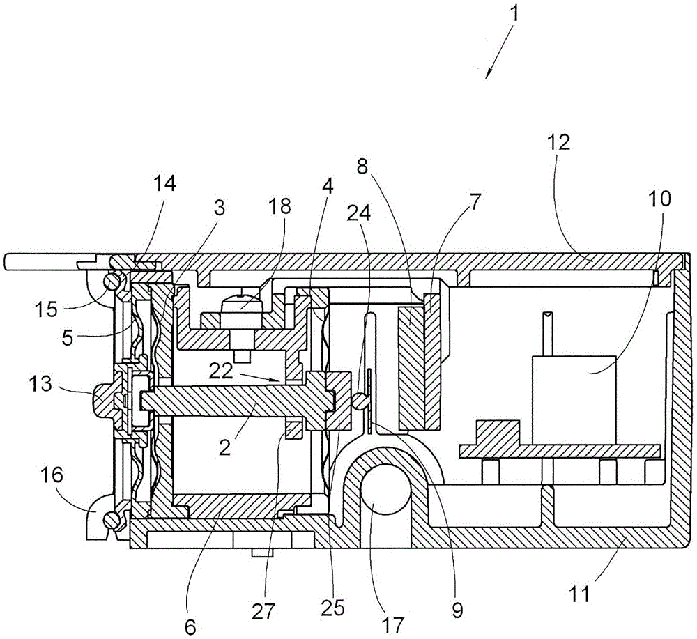
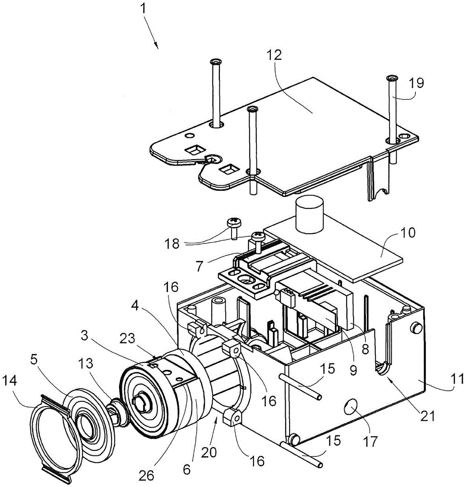
[0022] figure 1 and figure 2 A yarn tension sensor 1 according to the invention is shown for use at a winding machine station. The yarn tension sensor 1 has a housing 11 including a housing cover 12 . The housing cover 12 can be fixedly connected to the housing 11 by means of rivets 19 . The housing has holes 17 . By means of the holes 17 and matching screws, the housing 11 of the yarn tension sensor 1 can be fixed on the support of the winding machine station. Furthermore, the housing 11 has openings 21 for the lead-through of electrical wires. In addition to the components essential to the invention, which will be described in more detail below, evaluation electronics 10 are located in this housing.

[0023] The yarn tension sensor 1 has a rod-shaped force transmission element 2 . The two membranes 3 and 4 act as guides for the force transmission element 2 . These membranes are held by the sleeve 6 and are fixedly coupled thereto. Furthermore, in the region of the m...


PUM


Abstract

The sensor (1) has a rod-shaped force transmission element (2) whose one end is actively connected with a running thread. Guide units i.e. guide membranes (3, 4), guide the transmission element during moving towards a longitudinal axis transverse to a running direction of the thread. A measuring unit e.g. bending joist (9), is actively connected with another end of the force transmission element and accommodated at accommodating units. A cylindrical case (6) is secured at a housing for holding the guide units. The accommodating units are held by a rigid connection with the case. The accommodating units consists of a bracket (7) and a glass plate (8).

Description

technical field [0001] The invention relates to a yarn tension sensor for measuring the yarn tension of a moving yarn, comprising: a rod-shaped force transmitting member having a first end in operative connection with the moving yarn; a guide Mechanism, when the rod-shaped force-transmitting member moves along its longitudinal axis direction transverse to the yarn moving direction, the guide mechanism guides the rod-shaped force-transmitting member; Two ends are in operative connection; a mounting mechanism for mounting the measuring mechanism; and a housing, in which the rod-shaped force transmission member, the guiding mechanism, the measuring mechanism and the mounting mechanism are installed. Background technique [0002] Yarn tension sensors are used, for example, in winding machines which wind yarn from unwinding bobbins, such as bobbins, into winding bobbins (mostly cross-winding bobbins). Maintaining a predetermined yarn stress or yarn tension is of great importance...

Claims


Application Information

Patent Timeline
Patent Type & Authority Patents(China)
IPC IPC(8): G01L5/04
CPCB65H59/40B65H2701/31G01L1/04G01L5/102
Inventor 彼得·亨尼希迈克尔·伊丁弗兰克·勒文夫斯
Owner RIETER AUTOMATIC WINDER GMBH
Why Eureka
Try Eureka