Magnetic caliper with reference scale on edge

a magnetic caliper and reference scale technology, applied in the field of electromechanical sensing movement or position, can solve problems such as no clear advantages

Inactive Publication Date: 2009-05-12
MITUTOYO CORP
View PDF33 Cites 32 Cited by
  • Summary
  • Abstract
  • Description
  • Claims
  • Application Information

AI Technical Summary

Benefits of technology

[0007]The present invention is directed to an improved caliper configuration that provides certain cost and / or reliability advantages, and that enables the use of readhead and scale elements that have not been practical to use in known hand tool type caliper configurations. A caliper utilizing a high resolution magnetic scale track positioned along a reference edge of a scale member is provided.
[0008]In accordance with one aspect of the invention, the scale track may be located along an edge surface of the scale member that forms a sliding bearing with a mating surface of the caliper slide, thereby maintaining proper alignment of the slide jaw. Such an edge surface is therefore denoted a reference edge (also called a reference edge surface). In contrast, in known caliper configurations the scale track has been placed on the broad top surface of the scale member. Placing the scale track along the reference edge is advantageous in that the reference edge surface is inherently precisely machined. This is because the reference edge must guide the slide such that the measuring jaws of the caliper remain precisely parallel, to prevent measurement errors. Thus, the reference edge surface and the mating surface of the slide are inherently straight, smooth and flat. In addition, when the two surfaces slide against each other particles are excluded by the inherently close fit and the wiping action.
[0009]In accordance with another aspect of the invention, the readhead sensor may be mounted within the slide surface that mates to the reference edge. Thus, the readhead sensor may be reliably positioned at an extremely small gap relative to the scale, in a manner that is unprecedented in a hand tool type caliper configuration. Such a small gap allows an extremely small sensor to provide good signal strength and a high signal-to-noise ratio.
[0011]In accordance with another aspect of the invention, the extremely small gap between the readhead sensor and the scale track allow the use of previously-impractical miniature sensor technologies, such as miniature magnetic field sensors that require a close proximity between a magnetic scale and the sensor due to spacing loss.
[0015]According to this invention, a very small readhead sensor may be reliably positioned at an extremely small gap relative to the scale track in a protected operating environment, without detrimentally affecting cost, slider friction, or signal strength. High resolution digital signals may be provided from the readhead sensor, eliminating the need for analog signal interpolation in order to provide typical caliper measurement resolution.

Problems solved by technology

However, the disclosure of '402 patent discloses a “caliper” that is not compact, and furthermore offers no clear advantages over the conventional caliper configuration outlined above, for conventional hand tool type caliper applications.

Method used


Image

  • Magnetic caliper with reference scale on edge
  • Magnetic caliper with reference scale on edge
  • Magnetic caliper with reference scale on edge

Examples


Embodiment Construction

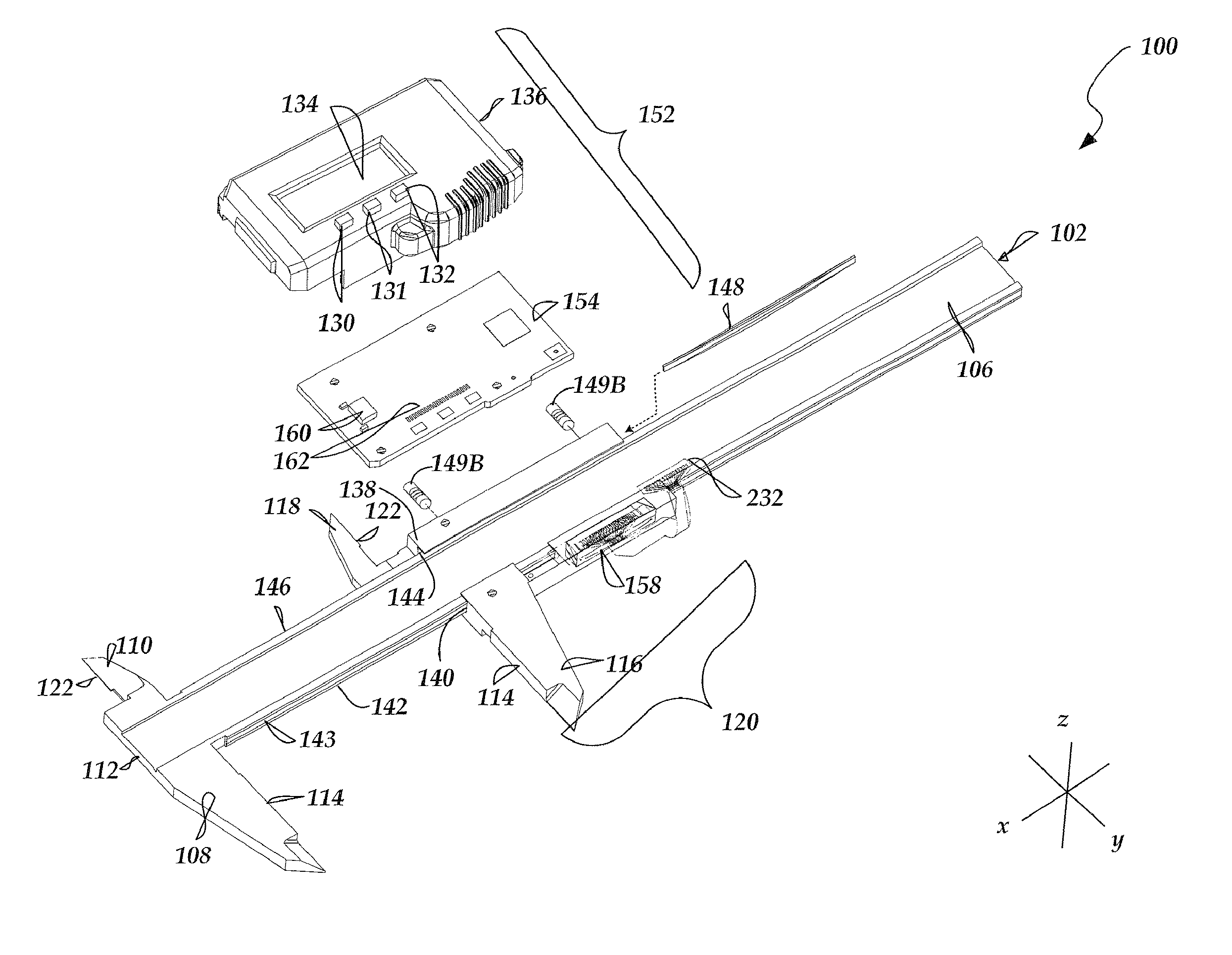
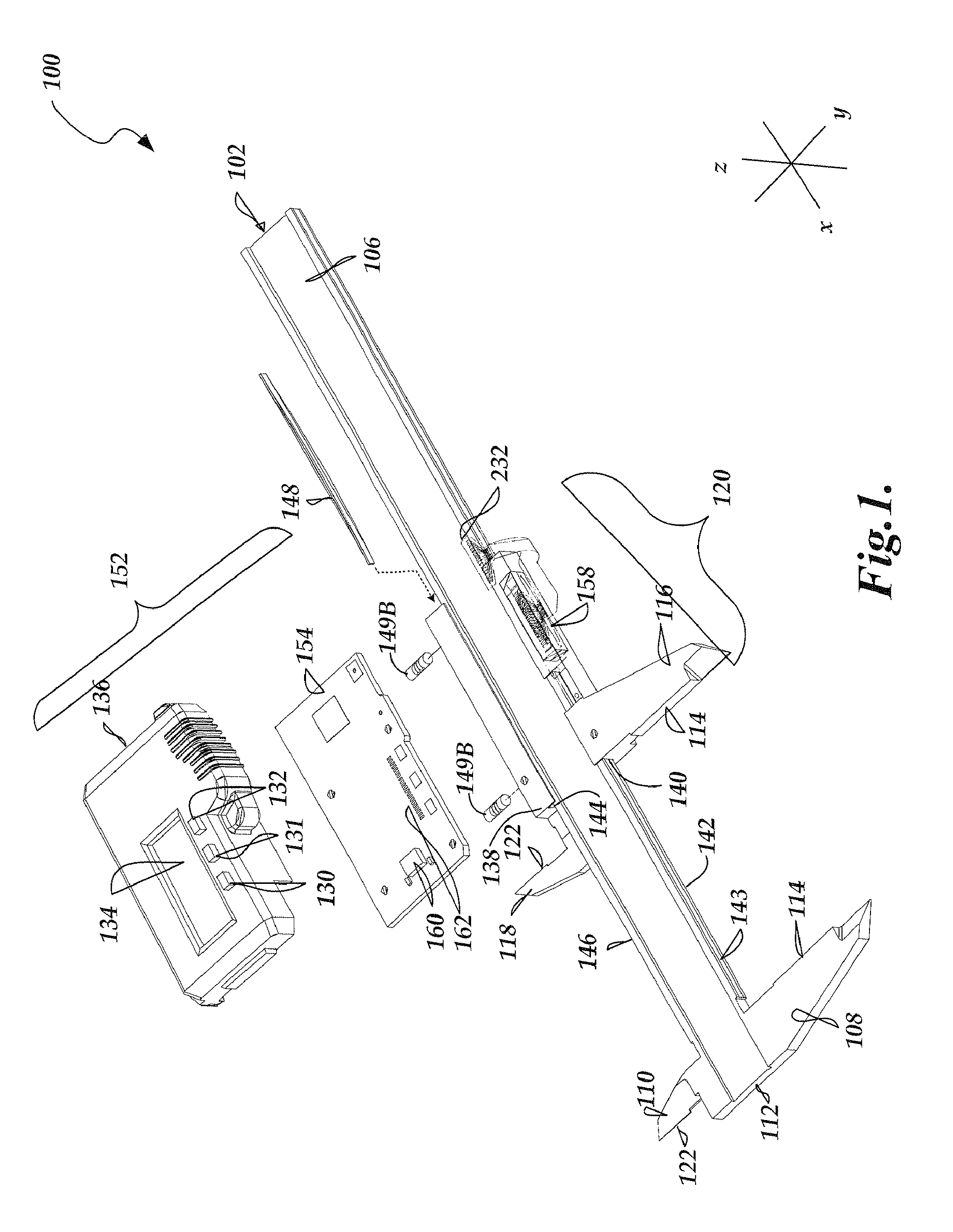
[0029]FIG. 1 is an exploded view diagram of a first exemplary embodiment of a hand tool type caliper 100 including a magnetic sensor assembly 158 and scale track 143 positioned along the reference edge surface 142 of an elongated scale member 102 in accordance with the present invention. The magnetic sensor assembly 158 is positioned in a slider 138 to form a slider assembly 120, to which an electronic assembly 152 is attached. A portion of the slider 138 is shown in wireform outline, to better illustrate the magnetic sensor assembly 158. The general mechanical structure and physical operation of the caliper 100 is similar to that of certain prior electronic calipers, such as that of U.S. Pat. No. 5,901,458, which is hereby incorporated by reference in its entirety. The scale member 102 is a rigid or semi-rigid bar having a generally rectangular cross section. In some embodiments, a groove 106 may be formed in its wide upper surface to accept an elongated thin substrate (not shown)....


PUM


Abstract

An electronic hand tool type caliper includes a scale track located along a scale member reference edge that forms a sliding bearing with a mating surface of the caliper slide, thereby maintaining proper alignment of the slide jaw. Placing the scale track along the reference edge is advantageous in that the reference edge surface is inherently precisely machined and particles are excluded by the inherently close fit and the wiping action of the sliding bearing. A readhead sensor is mounted within the slide surface that mates to the reference edge to provide the sliding bearing. Thus, a very small readhead sensor may be reliably positioned at an extremely small gap relative to the scale in a protected operating environment, without detrimentally affecting cost, slider friction, or signal strength. High resolution digital signals may be provided.

Description

FIELD OF THE INVENTION[0001]The invention relates generally to metrology systems, and more particularly to electronically sensing movement or position between two members such as the moving parts of a caliper.BACKGROUND OF THE INVENTION[0002]Various electronic calipers are known that use electronic position encoders. These encoders are generally based on low-power inductive, capacitive, or magnetic position sensing technology. In general, an encoder may comprise a readhead and a scale. The readhead may generally comprise a readhead sensor and readhead electronics. The readhead outputs signals that vary as a function of the position of the readhead sensor relative to the scale, along a measuring axis. In an electronic caliper the scale is generally affixed to an elongated scale member that includes a first measuring jaw and the readhead is affixed to a slide which is movable along the scale member and which includes a second measuring jaw. Thus, measurements of the distance between t...

Claims


Application Information

Patent Timeline
Patent Type & Authority Patents(United States)
IPC IPC(8): G01B7/14G01B7/02
CPCG01B3/205
Inventor MEICHLE, MICHAEL E.ATHERTON, KIM W.
Owner MITUTOYO CORP
Why Eureka
Try Eureka