
Device for measuring wood blocks and method

a technology for measuring devices and wood blocks, applied in the direction of distance measurement, mechanical measuring arrangements, instruments, etc., can solve the problems of inability to obtain special saw fixtures on the job site, the exact placement of the center of adjacent members at the specified distance is rarely perfect, and the width of the frame is typically wider than 11/, so as to achieve the effect of avoiding measurement errors and measuring and cutting blocks more accurately

Inactive Publication Date: 2004-02-03
CHILTON SEAN K
View PDF9 Cites 31 Cited by
  • Summary
  • Abstract
  • Description
  • Claims
  • Application Information

AI Technical Summary

Benefits of technology

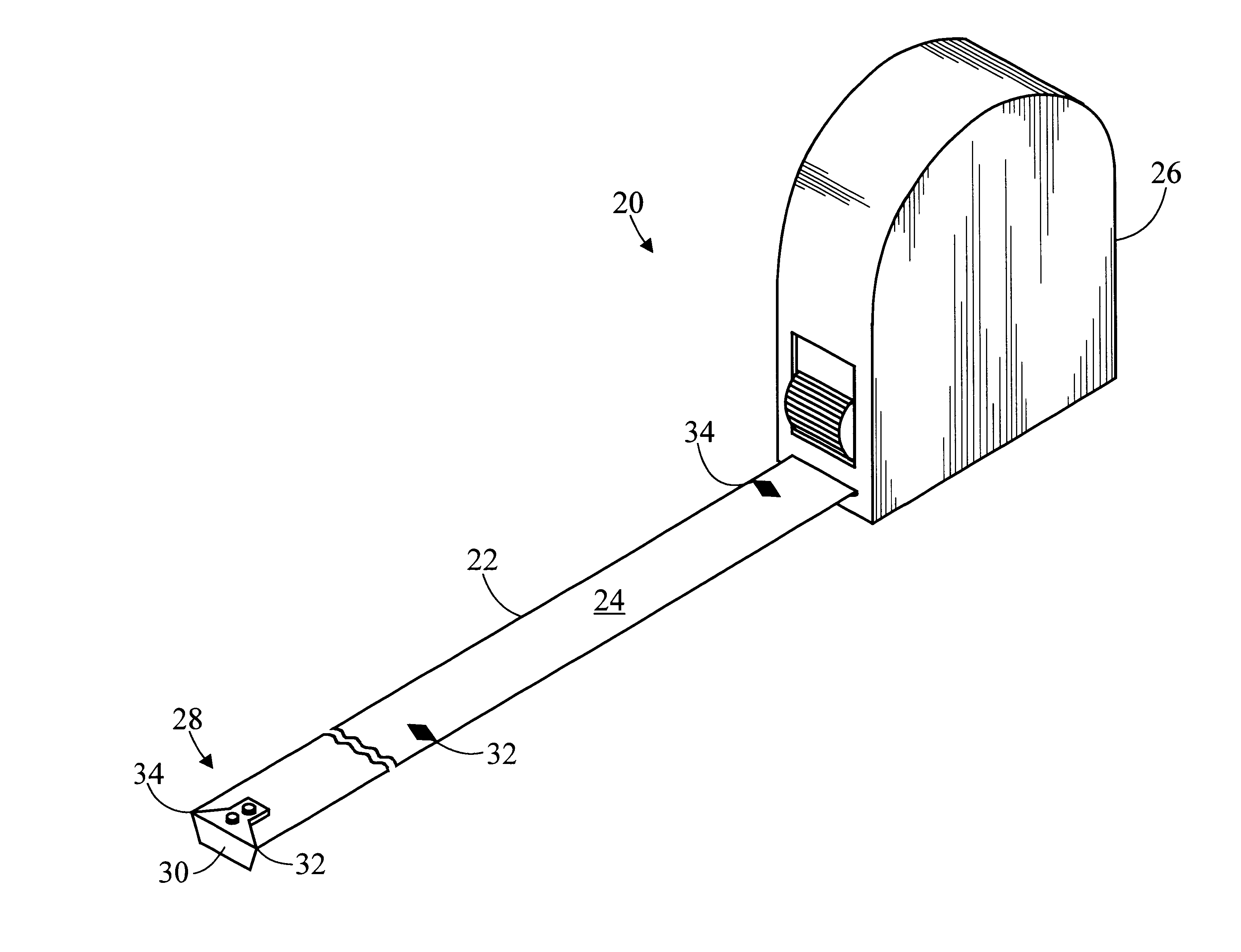
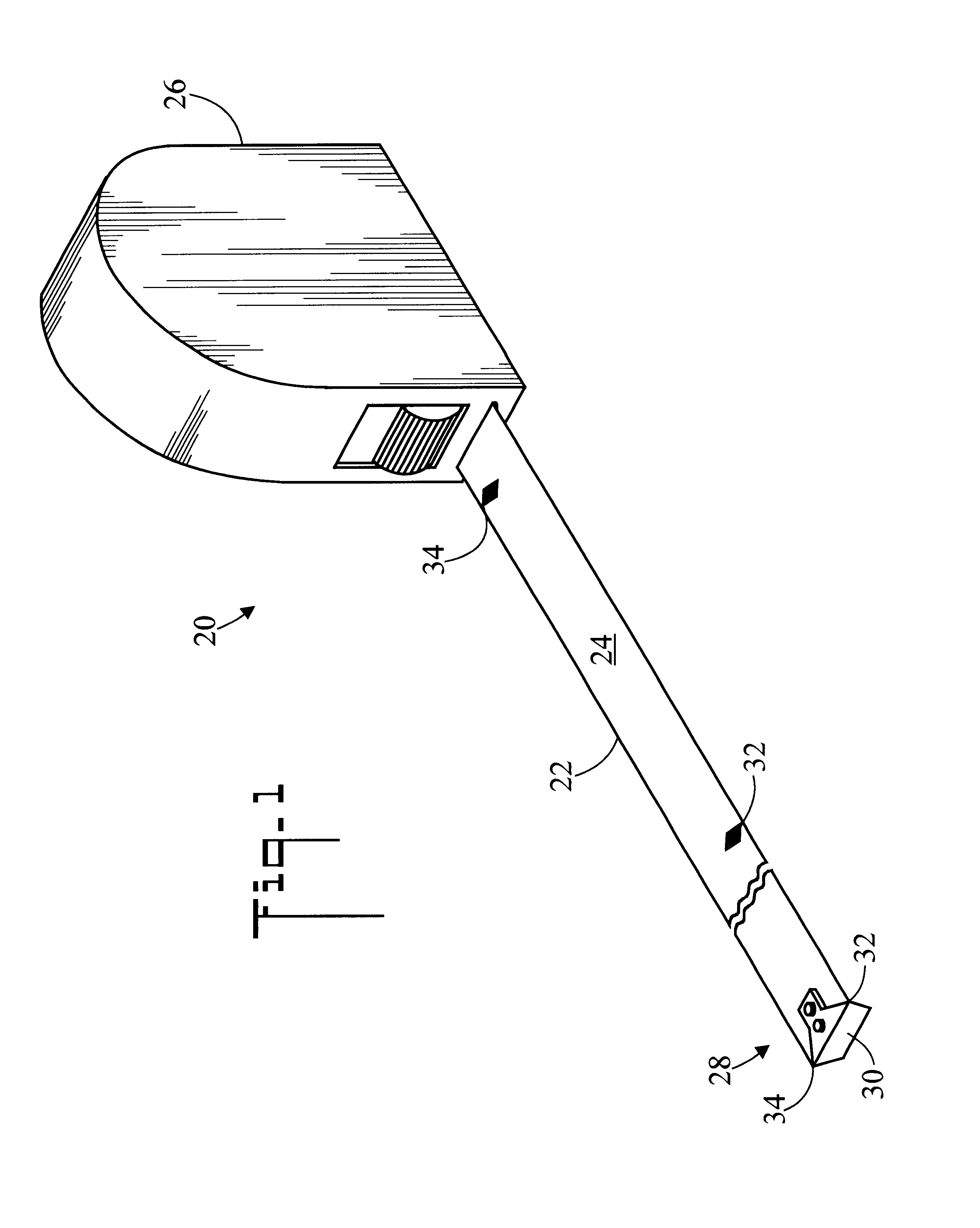
"The present invention is a device for measuring wood blocks used in construction. The device is a tape measure with special marks on it that allow for accurate measurements. The device is placed on a board and used to make marks on the board at desired intervals. The device helps to create blocks quickly and avoids measurement errors. The invention includes a first set of marks on the tape at 141 / 2 inches and a second set of marks at 221 / 2 inches. The device can also have conventional tape measure markings or marks in different embodiments. The technical effect of the invention is to provide a more accurate and efficient way to measure and cut wood blocks in construction."

Problems solved by technology

The framing lumber is, however, typically wider than 11 / 2 inches due to the original cut, being bowed, or being swollen due to moisture.
Also, exact placement of the centers of adjacent members at the specified distance is rarely perfect.
However, the special saw fixture is often not available at a job site.
The problem with this method of making one block at a time is that it is very tedious and time consuming.
The problem with the second method is inaccuracy.
Each time the carpenter moves the pattern block down the length of the board, there is opportunity for measurement error.
As a result, the second method typically produces blocks of inaccurate lengths that do not properly fit between the framing members.

Method used


Image

  • Device for measuring wood blocks and method
  • Device for measuring wood blocks and method
  • Device for measuring wood blocks and method

Examples


second embodiment

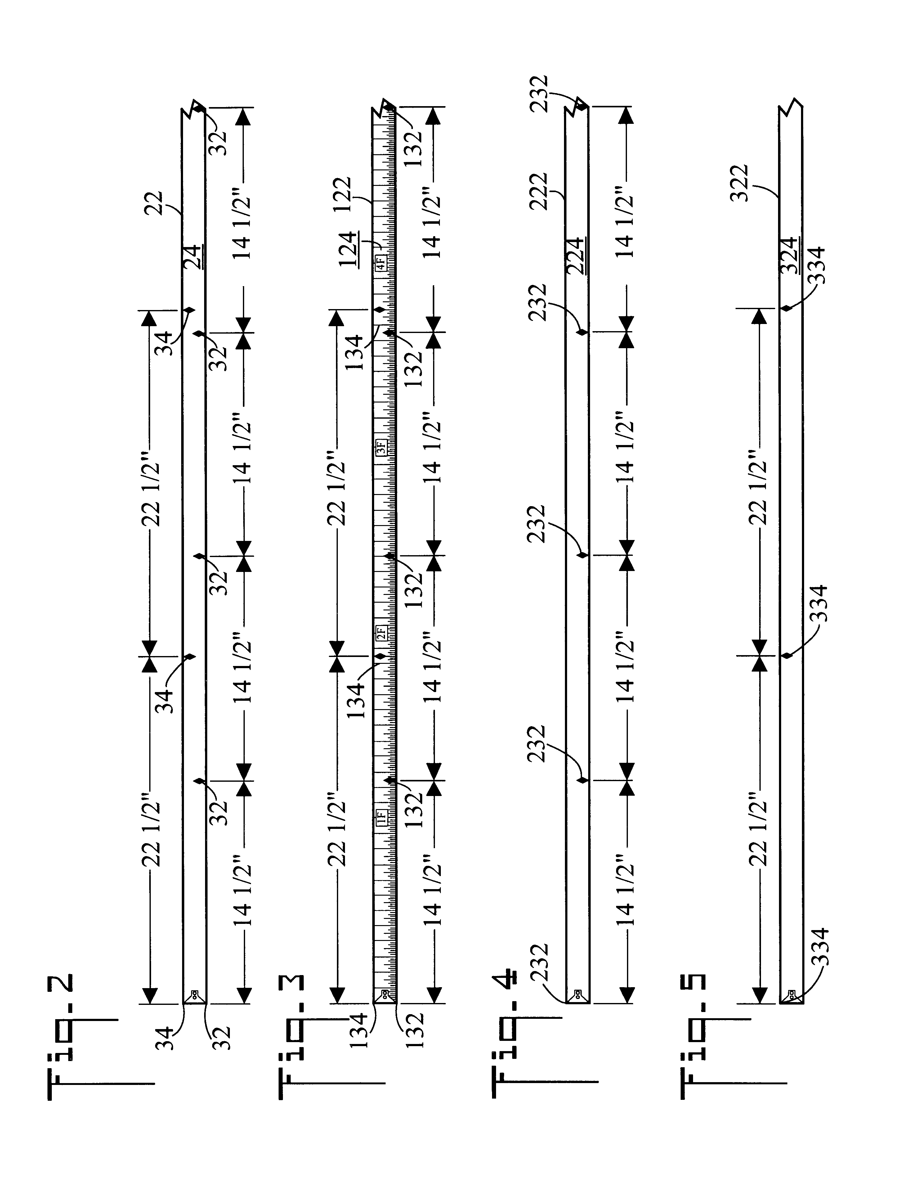
FIG. 3 is a reduced fragmented top plan view of the tape, generally designated as 122. In tape 122, conventional tape measure markings are also disposed on surface 124 of tape 122 for convenience.

third embodiment

FIG. 4 is a reduced fragmented top plan view of the tape, generally designated as 222. Tape 222 only has first spaced stations 232 disposed on surface 224 of tape 222. These are the only spaced stations disposed on surface 224 of tape 222.

fourth embodiment

FIG. 5 is a reduced fragmented top plan view of the tape, generally designated as 322. Tape 322 only has second spaced stations 334 disposed on surface 324. These are the only spaced stations disposed on surface 324 of tape 222.

FIG. 6 is a reduced fragmented top plan view of tape 22 placed upon a board 500 (such as an elongated two-by-four). Free end 28 of tape 22 has been placed at end 501 of board 500. Tape 22 has been used to make marks 36 at 141 / 2 inch intervals.

FIG. 7 is a reduced fragmented top plan view of board 500 and marks 36.

FIG. 8 is an enlarged view of area 8 of FIG. 7 showing a saw blade 502 registered against first mark 36. Saw blade 502 has been registered against line 36 so that a cut will subtract width W of blade 502 from first block 40. That is, the right side of blade 502 is aligned with mark 36, so the cut is made toward end 501. This is defined as making a "back cut." In this fashion, first block 40 will be 141 / 2 inches minus width W (about 3 / 32 inches) inches...


PUM


Abstract

A special tape (22) for measuring blocks used in the construction of wood structures includes two special scales. A first scale has marks (32) spaced at 14½ inch intervals for making blocks for studs, and a second scale has marks (34) spaced at 22½ inch intervals for making blocks for rafters. The tape (22) is longitudinally placed along a two-by board (500) and marks (36) made on the two-by board (500) at the desired intervals of 14½ or 22½ inches. The two-by board (500) is then cut at the marks (36) to create the blocks, which are then placed between the studs or rafters.

Description

The present invention pertains generally to construction of wood buildings, and more particularly to a tape that may be used to accurately measure the structural blocks that are placed between adjacent wall studs, roof rafters, ceiling joists, and floor joists.Wood buildings are built by assembling individual studs, headers, rafters, etc. into walls, ceilings, floors, and roofs. All dimensions are set by the UBC (Uniform Building Code). Most floors, roofs, ceilings, and walls are built using two-by (2.times.) dimensional framing lumber. For example, 2 by 4 lumber may be used in walls, 2 by 12 lumber may be used in floors, and 2 by 8 lumber may be used in roofs. The UBC requires that these wall stud, floor joist, and roof rafter framing members be placed on 16 inch centers. This means that the centers of the boards must be 16 inches apart. Other centers are sometimes specified. For example, the UBC requires that truss roof framing members be placed on 24 inch centers.Conventional tap...

Claims


Application Information

Patent Timeline
Patent Type & Authority Patents(United States)
IPC IPC(8): G01B3/00G01B3/10G01B3/02
CPCG01B3/004G01B3/1082G01B3/1003
Inventor CHILTON, SEAN K.
Owner CHILTON SEAN K
Learn More