Measuring device and measuring method for diffraction efficiency of grating

A grating diffraction and measurement device technology, which is applied in the direction of testing optical performance, etc., can solve the problems of large measurement errors, low measurement efficiency, and difficulty in detecting guided mode resonance information, so as to avoid energy loss and reduce measurement blind spots.

Inactive Publication Date: 2009-09-30
SHANGHAI INST OF OPTICS & FINE MECHANICS CHINESE ACAD OF SCI
View PDF0 Cites 31 Cited by
  • Summary
  • Abstract
  • Description
  • Claims
  • Application Information

AI Technical Summary

Problems solved by technology

[0006] 1) The measurement efficiency is very low. Every time a parameter of an input wavelength is adjusted, it is necessary to calculate the angle and manually change the position of the detector;
[0007] 2) The measurement error is large. When manually adjusting the position of the detector, measurement errors will be introduced due to the distance between the detector and the grating or the deviation of the detection angle;
[0008] 3) The measurement data is incomplete. When measuring the anomaly of the guided mode resonance in the grating diffraction spectrum, since the anomaly of the guided mode resonance is very sensitive to the wavelength and angle of the incident light, generally less than 0.1nm or 0.1 degree, it is difficult to detect it by manually adjusting the detector position Guided Mode Resonance Information

Method used


Image

  • Measuring device and measuring method for diffraction efficiency of grating
  • Measuring device and measuring method for diffraction efficiency of grating
  • Measuring device and measuring method for diffraction efficiency of grating

Examples


Embodiment Construction

[0037] The present invention will be further described below in conjunction with the embodiments and accompanying drawings, but the protection scope of the present invention should not be limited thereby.

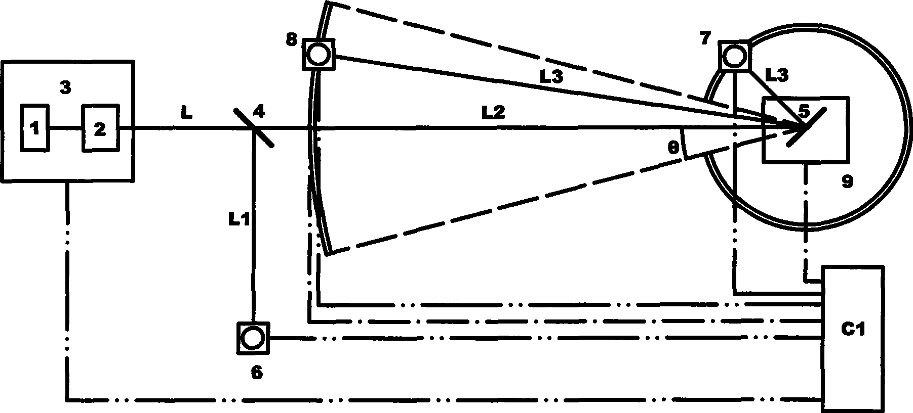
[0038] see first figure 1 , figure 1 A schematic diagram of the grating diffraction efficiency measurement device of the present invention is provided, as can be seen from the figure, the measurement device of the grating diffraction efficiency of the present invention includes:

[0039] A monochromatic light source 3, the monochromatic light source 3 is composed of a broadband light source 1 and a monochromator 2, and scans and outputs monochromatic light in a certain wavelength range. There is a beam splitter 4 along the output direction of the monochromatic light beam L of the monochromatic light source 3. The beam splitter 4 divides the monochromatic light beam L into a first light beam L1 and a second light beam L2. The detector 6, in the output direction of the seco...


PUM


Abstract

The invention relates to a measuring device and a measuring method for the diffraction efficiency of a grating. The device comprises a monochromatic source, a beam splitter, a grating rotary table, detectors, a two-dimensional translation platform and a computer. The method is characterized in that: the second detector and the third detector are adopted to move on a small arc and a big arc respectively to detect the energy of a diffracted beam L3 of the grating to be tested; and the method realizes the aims of diminishing a measurement blind zone and reducing the requirement on the size of an optical platform. The double light path synchronous measurement is adopted to remove measurement errors caused by the instability of the light source.

Description

technical field [0001] The invention relates to grating diffraction efficiency, in particular to a measuring device and method for grating diffraction efficiency. The measuring device of the invention realizes automatic scanning measurement of grating diffraction efficiency within a certain incident wavelength range or incident angle range. Background technique [0002] The non-zero diffraction angle of a grating changes with the wavelength of the incident light. When the grating period is large (more than 3 times greater than the incident center wavelength), the diffraction angle for a certain order does not change significantly with the wavelength. For such a grating, a detector with a larger detection surface can be used to complete the measurement of the diffraction efficiency of a certain diffraction order in a certain wavelength range at a fixed position. However, when the grating period is sub-wavelength, generally there are only two diffraction orders -1 and 0. Whe...

Claims


Application Information

Patent Timeline
Patent Type & Authority Applications(China)
IPC IPC(8): G01M11/02
Inventor 汪剑鹏麻健勇晋云霞刘光辉邵建达范正修
Owner SHANGHAI INST OF OPTICS & FINE MECHANICS CHINESE ACAD OF SCI
Why Eureka
Try Eureka