Tetra-nocular camera positioning device and method

A positioning device and positioning method technology, applied in image enhancement, image analysis, image data processing, etc., can solve the problem of small longitudinal field of view of binocular cameras, and achieve the effects of increasing the camera range, optimizing experience effects, and accurate positioning

Pending Publication Date: 2017-05-31
VR TECH HLDG LTD
View PDF0 Cites 0 Cited by
  • Summary
  • Abstract
  • Description
  • Claims
  • Application Information

AI Technical Summary

Problems solved by technology

[0003] In order to solve the defect of the current binocular camera with a small longitudinal field of view, the present invention provides a positioning device and method for a four-eye camera with a large longitudinal field of view

Method used


Image

  • Tetra-nocular camera positioning device and method
  • Tetra-nocular camera positioning device and method
  • Tetra-nocular camera positioning device and method

Examples


Embodiment Construction

[0018] In order to solve the defect of the current binocular camera with a small longitudinal field of view, the present invention provides a positioning device and method for a quadruple camera with a large longitudinal field of view.

[0019] In order to have a clearer understanding of the technical features, purposes and effects of the present invention, the specific implementation manners of the present invention will now be described in detail with reference to the accompanying drawings.

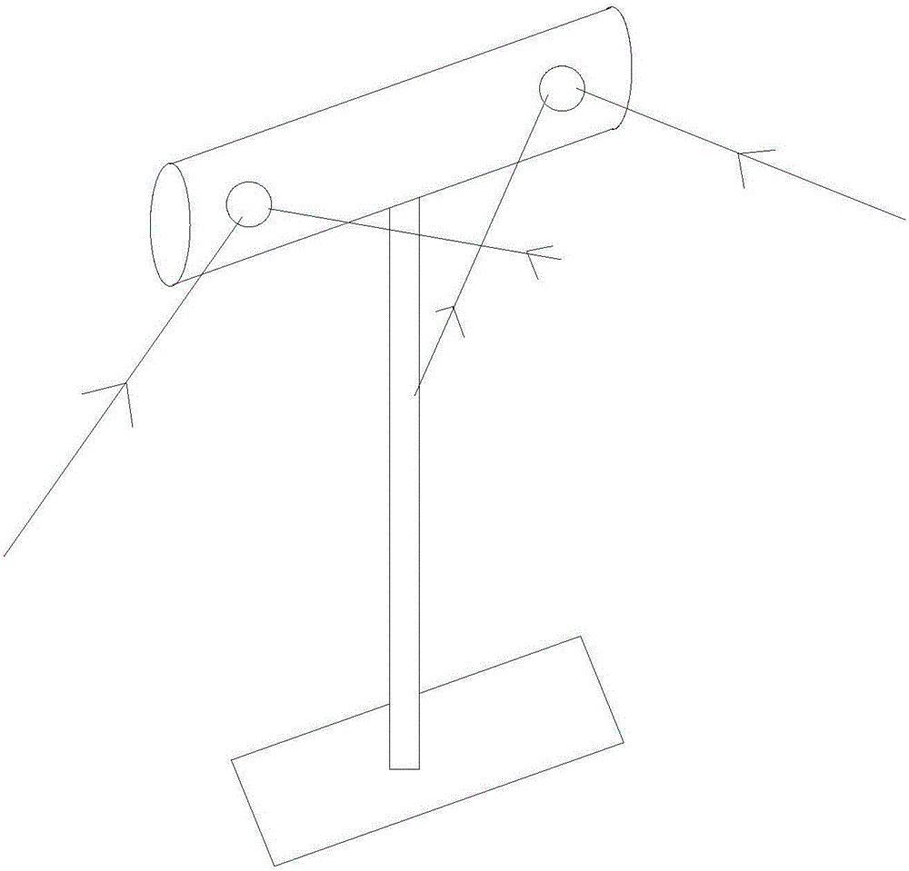
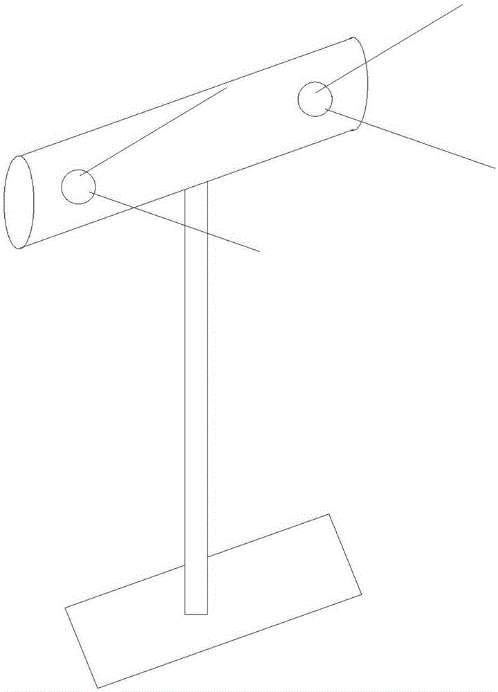
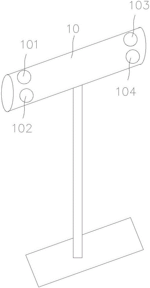
[0020] see image 3 — Figure 4 , the four-eye camera positioning device of the present invention comprises four-eye camera 10, and four-eye camera comprises four cameras, and four cameras are positioned at the four corners of four-eye camera 10 respectively, are left upper camera 101, left lower camera 102, right upper camera 103, right lower camera 104. Wherein, the upper left camera 101 and the upper right camera 103 form a pair of binocular cameras, which we call the upper binocul...


PUM


Abstract

The invention provides a tetra-nocular camera positioning device. The device comprises a left upper camera, a left lower camera, a right upper camera and a right lower camera, wherein an upper binocular camera is formed by the left upper camera and the right upper camera, and a lower binocular camera is formed by the left lower camera and the right lower camera; and the upper binocular camera faces upwards, while the lower binocular camera faces downwards. Compared with the prior art, the tetra-nocular camera positioning device has the advantages that the tetra-nocular camera is formed by four cameras, and the pitching angle and camera interval are accurately designed, so that the measurement blind zone is as small as possible while the longitudinal vision of the tetra-nocular camera is enlarged, the shooting range of the tetra-nocular camera is greatly increased, and the experience effect is optimized.

Description

technical field [0001] The present invention relates to the field of near-eye display devices, and more specifically, to a four-eye camera positioning device and method. Background technique [0002] The spatial positioning of near-eye display devices or handles is a core technology of virtual reality. A practical solution is to set a light source on the helmet, and then use a binocular camera to capture the projection of the light source on the image. If at least three light sources and projections are known The corresponding relationship, and then call the PnP algorithm to get the spatial positioning of the helmet. Usually, the camera we use is a binocular camera, such as figure 1 As shown in , two cameras with the same parameters are placed side by side and parallel to the horizon. This kind of binocular camera has the defect that the longitudinal field of view is small when positioning ( figure 2 ), when the user’s vertical use range exceeds the binocular camera area...

Claims


Application Information

Patent Timeline
Patent Type & Authority Applications(China)
IPC IPC(8): G06T7/70
CPCG06T2207/30244
Inventor 罗毅肖迟
Owner VR TECH HLDG LTD
Why Eureka
Try Eureka