
Goaf disaster analysis device based on thermal imaging principle

An analysis device and thermal imaging technology, applied in closed-circuit television systems, supporting machines, mechanical equipment, etc., can solve problems such as increasing hidden dangers, unfavorable disaster analysis, and inability to monitor goaf areas, and achieve the effect of increasing the camera range

Pending Publication Date: 2018-12-11
KUNMING PROSPECTING DESIGN INST OF CHINA NONFERROUS METALS IND +1
View PDF0 Cites 0 Cited by
  • Summary
  • Abstract
  • Description
  • Claims
  • Application Information

AI Technical Summary

Problems solved by technology

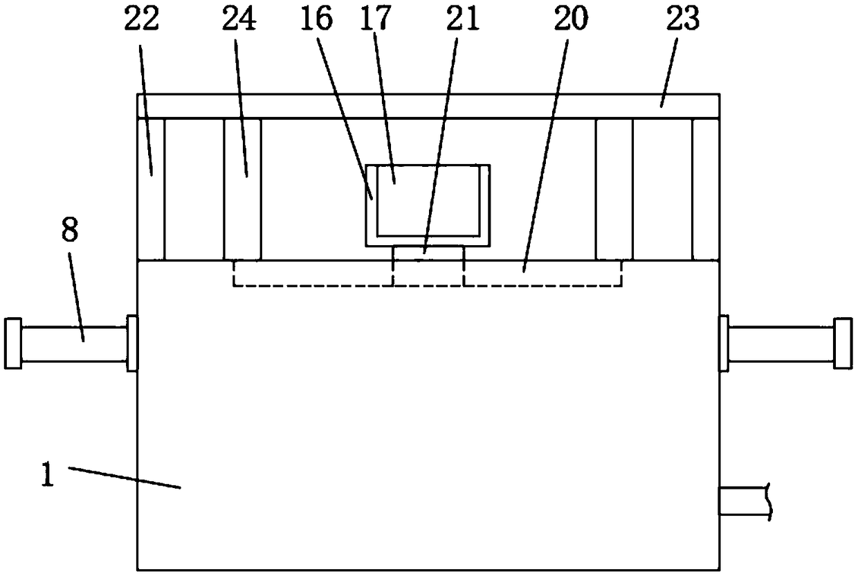
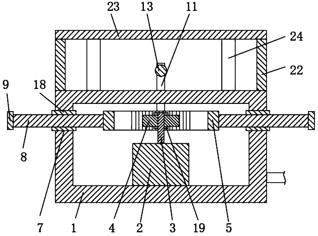
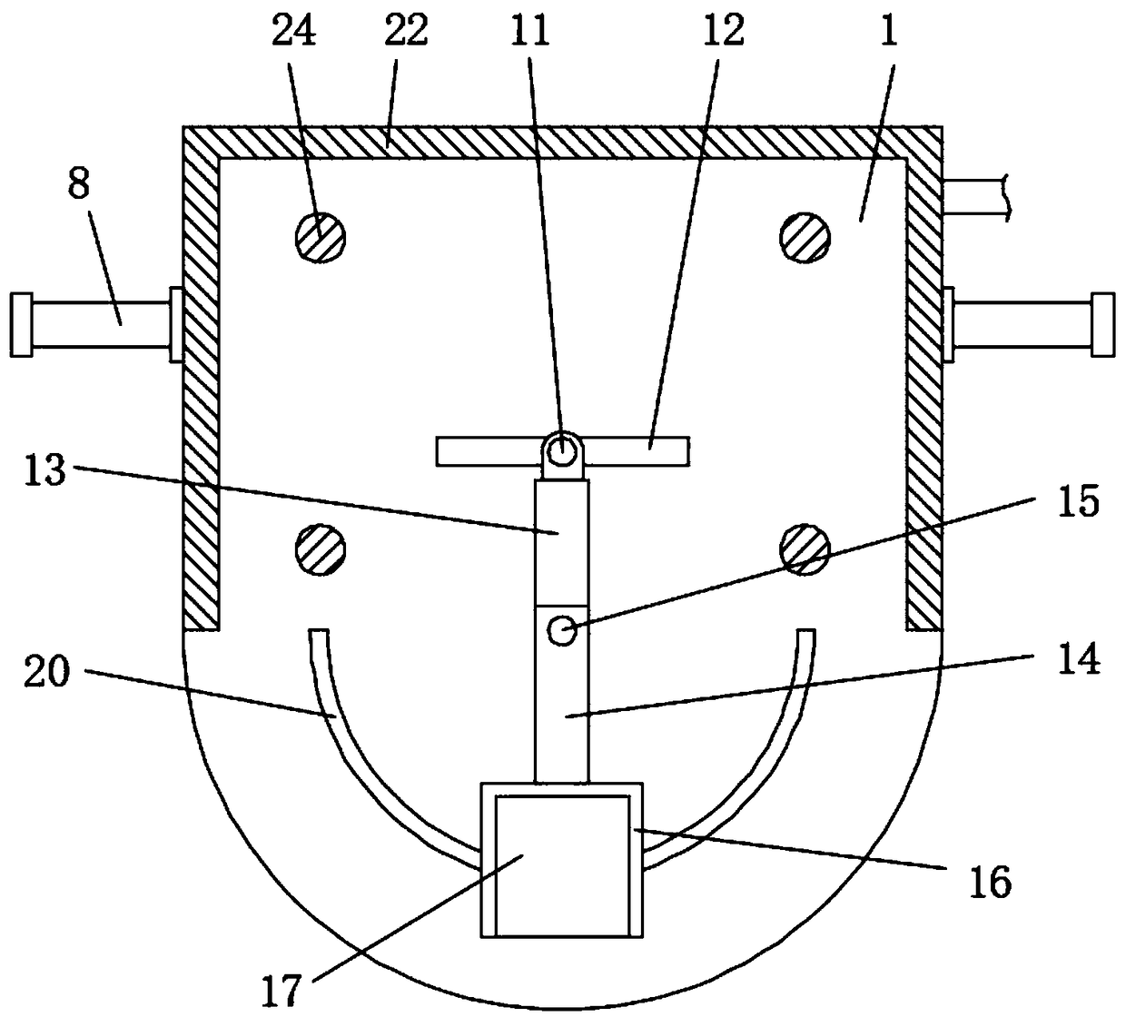
[0002] The goaf is a "hole" created by man-made excavation or natural geological movement below the surface. The existence of the goaf makes the safe production of the mine face a great safety problem. Personnel and mechanical equipment may fall into the goaf and be damaged. Therefore, the disaster monitoring and analysis equipment inside the goaf needs to be installed outside the goaf, and the thermal imaging equipment is generally used for monitoring and analyzing the disaster inside the goaf, and the thermal imaging equipment can only detect one However, since the goaf is generally large, static thermal imaging equipment cannot monitor the entire goaf, which is not conducive to subsequent disaster analysis and increases hidden dangers. If a thermal imaging device can be designed Swing, and then a device that can monitor the entire goaf can solve such problems. Therefore, we propose a goaf disaster analysis device based on the principle of thermal imaging

Method used


Image

  • Goaf disaster analysis device based on thermal imaging principle
  • Goaf disaster analysis device based on thermal imaging principle
  • Goaf disaster analysis device based on thermal imaging principle

Examples


Embodiment Construction

[0021] In order to make the purpose, technical solutions and advantages of the embodiments of the present invention more clear, the technical solutions in the embodiments will be clearly and completely described below in conjunction with the drawings in the embodiments of the present invention. The following embodiments are used to illustrate the present invention , but not to limit the scope of the present invention.

[0022] In the description of the present invention, it should be noted that the terms "upper", "lower", "front", "rear", "left", "right", "vertical", "inner", "outer" etc. The indicated orientation or positional relationship is based on the orientation or positional relationship shown in the drawings, and is only for the convenience of describing the present invention and simplifying the description, rather than indicating or implying that the referred device or element must have a specific orientation, or in a specific orientation. construction and operation, ...


PUM


Abstract

The invention discloses a goaf disaster analysis device based on a thermal imaging principle. The goaf disaster analysis device based on the thermal imaging principle comprises a bottom block and a movable plate; a stepping motor is fixedly installed on the lower side wall of an inner cavity of the bottom block; a gear is assembled to the outer side wall of a rotating shaft; one end of a telescopic rod is hinged to the outer side wall of a fixed rod; a rotating plate is fixedly installed at the other end of the telescopic rod; and a thermal imaging camera is fixedly installed on the inner sidewall of a storage box. Through the structure of the stepping motor, the rotating shaft, the gear, the movable plate, the fixed rod, the telescopic rod, the rotating plate, the storage box and the thermal imaging camera, after the stepping motor is controlled to rotate through a computer, due to engagement of the gear and the movable plate, the movable plate and the fixed rod reciprocate left andright by rotating the gear, then the telescopic rod, the rotating plate, the storage box and the thermal imaging camera swing in a reciprocating mode along a fixed shaft, the shooting range of the thermal imaging camera is extended accordingly, energy generated by crushing of rock is captured for forming thermal images, and a whole goaf can be monitored and analyzed.

Description

technical field [0001] The invention relates to the technical field of goaf equipment, in particular to a goaf disaster analysis device based on the thermal imaging principle. Background technique [0002] The goaf is a "hole" created by man-made excavation or natural geological movement below the surface. The existence of the goaf makes the safe production of the mine face a great safety problem. Personnel and mechanical equipment may fall into the goaf and be damaged. Therefore, the disaster monitoring and analysis equipment inside the goaf needs to be installed outside the goaf, and the thermal imaging equipment is generally used for monitoring and analyzing the disaster inside the goaf, and the thermal imaging equipment can only detect one However, since the goaf is generally large, static thermal imaging equipment cannot monitor the entire goaf, which is not conducive to subsequent disaster analysis and increases hidden dangers. If a thermal imaging device can be design...

Claims


Application Information

Patent Timeline
Patent Type & Authority Applications(China)
IPC IPC(8): F16M11/18F16M11/06H04N7/18
CPCF16M11/18F16M11/06H04N7/18
Inventor 张向阳速田勇杨恩周罕雍伟勋董恒文李家寿张文方林进杰汪德文迟宽平何从星
Owner KUNMING PROSPECTING DESIGN INST OF CHINA NONFERROUS METALS IND
Learn More