Moving object imaging apparatus and moving object imaging method

A technology for camera devices and moving objects, applied in measuring devices, installations, image communications, etc., can solve the problems of limited monitoring range and poor response speed, and achieve the effect of expanding the camera range and avoiding response delays

Inactive Publication Date: 2019-10-11
HITACHI LTD
View PDF9 Cites 1 Cited by
  • Summary
  • Abstract
  • Description
  • Claims
  • Application Information

AI Technical Summary

Problems solved by technology

[0009] However, in the imaging device of Patent Document 1, since the movable range of the optical axis of the imaging device is limited by the narrow movable range of the mirror, there is a problem that the monitoring range is also inevitably limited.
[0010] In addition, the imaging device of Patent Document 2 is as follows from the document figure 1 and Figure 8 As clarified by et al., as a result of the built-in condenser lens and reflector, the scanning mechanism is configured to scan the entire camera, which is heavy in weight. In addition to the same problem as in Patent Document 1 that the practical imaging range is limited, the direction in which the optical axis of the imaging element is moved by the scanning of the scanning mechanism part has to scan the entire camera with a large weight. In such a structure, there is also the problem that the response speed will not improve.

Method used


Image

  • Moving object imaging apparatus and moving object imaging method
  • Moving object imaging apparatus and moving object imaging method
  • Moving object imaging apparatus and moving object imaging method

Examples


Embodiment 1

[0045] use Figure 1 to Figure 4 The moving object imaging device 1 according to the first embodiment of the present invention which follows a moving object such as a car or a person moving on a plane will be described.

[0046]

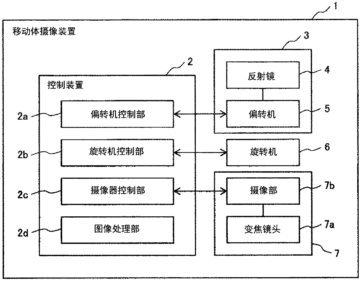
[0047] figure 1 It is a functional block diagram of the moving object imaging device 1 of this embodiment. As shown here, the mobile imaging device 1 includes: a deflection unit 3 composed of a mirror 4 and a deflection unit 5; a rotation unit 6 for rotating the deflection unit 3; and a video camera composed of a zoom lens 7a and an imaging unit 7b. 7; and the control device 2 for controlling them. In addition, a current motor (Galvano motor) is used as a power source of the deflection machine 5, and an angle detection unit is provided. As the power source of the rotating machine 6, a stepping motor or the like which can observe the rotation angle or the number of rotations is used. In addition, the imaging unit 7b includes an imaging element s...

Embodiment 2

[0065] Next, use Figure 5 The moving object imaging device 1 of Example 2, which is a modified example of Example 1, will be described. In addition, overlapping descriptions of the points common to Embodiment 1 are omitted.

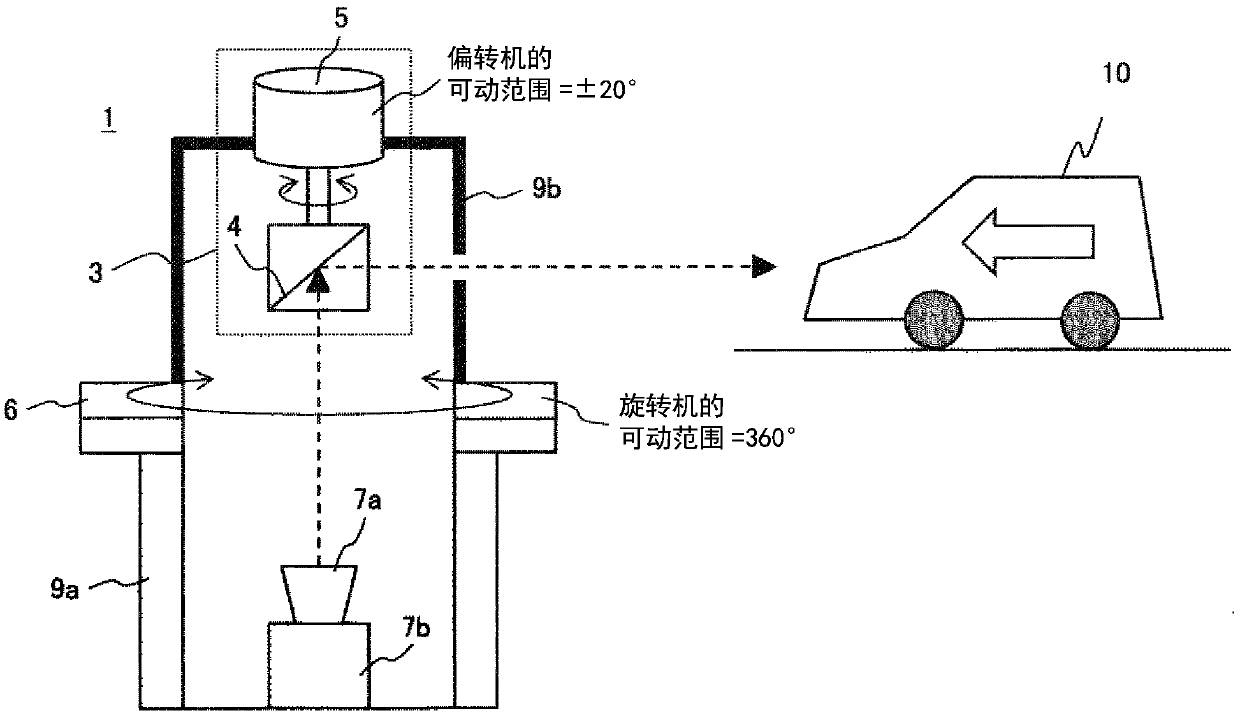
[0066] In Example 1, such as figure 2 The deflection machine 5 and the rotation machine 6 are arranged in such a way that the rotation axes of the deflection machine 5 and the rotation machine 6 coincide with the optical axis of the camera 7, but in this embodiment, as Figure 5 The deflection machine 5 and the rotation machine 6 are arranged so that the rotation axis of the rotation machine 6 coincides with the optical axis of the camera 7 and the rotation axes of the deflection machine 5 and the rotation machine 6 become parallel. In addition, a reflection mirror 4 a rotationally driven by a deflection machine 5 and a fixed reflection mirror 4 b are provided in the deflection unit 3 .

[0067] Thus, by configuring the moving body 10 to be imaged vi...

Embodiment 3

[0070] Next, use Figure 6 A moving object imaging device 1 according to a third embodiment of the present invention will be described. In addition, overlapping descriptions of points common to the above-described embodiments are omitted.

[0071] The moving object imaging device 1 of Embodiment 1 and Embodiment 2 is an imaging device that follows a moving body 10 such as a car or a person moving on a plane and performs imaging, but the moving object imaging device 1 of this embodiment follows a moving object 10 freely in three-dimensional space. An imaging device that takes an image of a moving body 10 such as a flying drone.

[0072] Therefore, in the moving object imaging device 1 of this embodiment, the deflection unit 3 is provided with a deflection unit 5a having a rotation axis parallel to the rotation axis of the rotation unit 6 and a deflection unit 5a having a rotation axis perpendicular to the rotation axis of the rotation unit 6 . Machine 5b, the deflection angle...


PUM


Abstract

The invention provides a moving object imaging apparatus and a moving object imaging method. Provided is a moving object monitoring device capable of tracking a high-speed moving object and having a large monitoring range. The moving object imaging apparatus includes: an imager that captures an image of a moving object; a first housing that has the imager fixed therein; a first reflecting mirror and a second reflecting mirror that are disposed on an optical axis of the imager; a second housing that houses the first reflecting mirror and the second reflecting mirror; a first deflector that is provided in the second housing and deflects the optical axis of the imager by rotating the first reflecting mirror; and a first rotator that rotates the second housing around the optical axis of the imager with respect to the first housing. A rotation axis of the first deflector and a rotation axis of the first rotator are parallel to each other.

Description

technical field [0001] The present invention relates to a moving object imaging device and a moving object imaging method that follow a moving object and perform imaging. Background technique [0002] Conventionally, there are known devices that capture images of moving objects such as automobiles and flying objects moving in a target area. In order to capture images following a moving object, it is necessary to control the optical axis of the camera so that the moving object is captured within the imaging range of the camera. As a method of directing the optical axis of the camera toward the moving body, there is known a method of making the optical axis of the camera follow the moving body by driving a plurality of rotatable movable mirrors with motors having different rotation axes. [0003] This technique is disclosed, for example, in Patent Document 1, and the abstract of the document states that "a light-transmitting window W1 is provided in a light-impermeable housin...

Claims


Application Information

Patent Timeline
Patent Type & Authority Applications(China)
IPC IPC(8): H04N7/18H04N5/225
CPCH04N7/18H04N23/54H04N23/55G02B7/1821G02B26/105G01S3/7864G01S3/789G02B27/0977G01S7/481H04N23/681H04N23/51H04N23/80
Inventor 松家大介三村昌弘日野一彦藤村高之
Owner HITACHI LTD
Why Eureka
Try Eureka