
Single button, cyclic shower head switch

a cyclic switch and single button technology, applied in the direction of multiple way valves, mechanical devices, valve operating means/releasing devices, etc., can solve the problems of kitchen shower head, hard switching, and traditional faucets cannot meet people's needs more, and achieve simple assembly, long service time, and relatively stable structure

Active Publication Date: 2018-09-04
XIAMEN SOLEX HIGH TECH IND CO LTD
View PDF13 Cites 4 Cited by
  • Summary
  • Abstract
  • Description
  • Claims
  • Application Information

AI Technical Summary

Benefits of technology

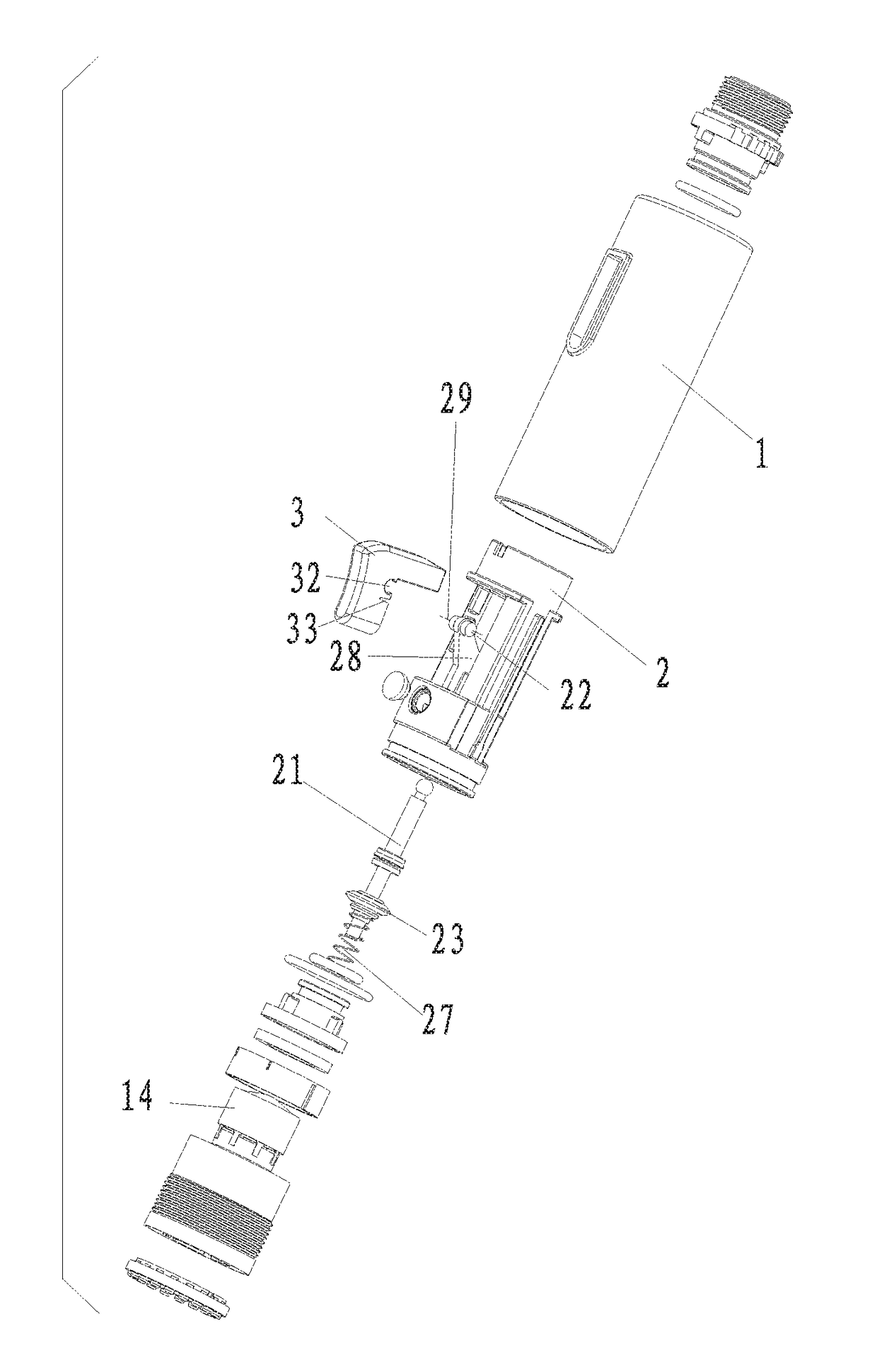
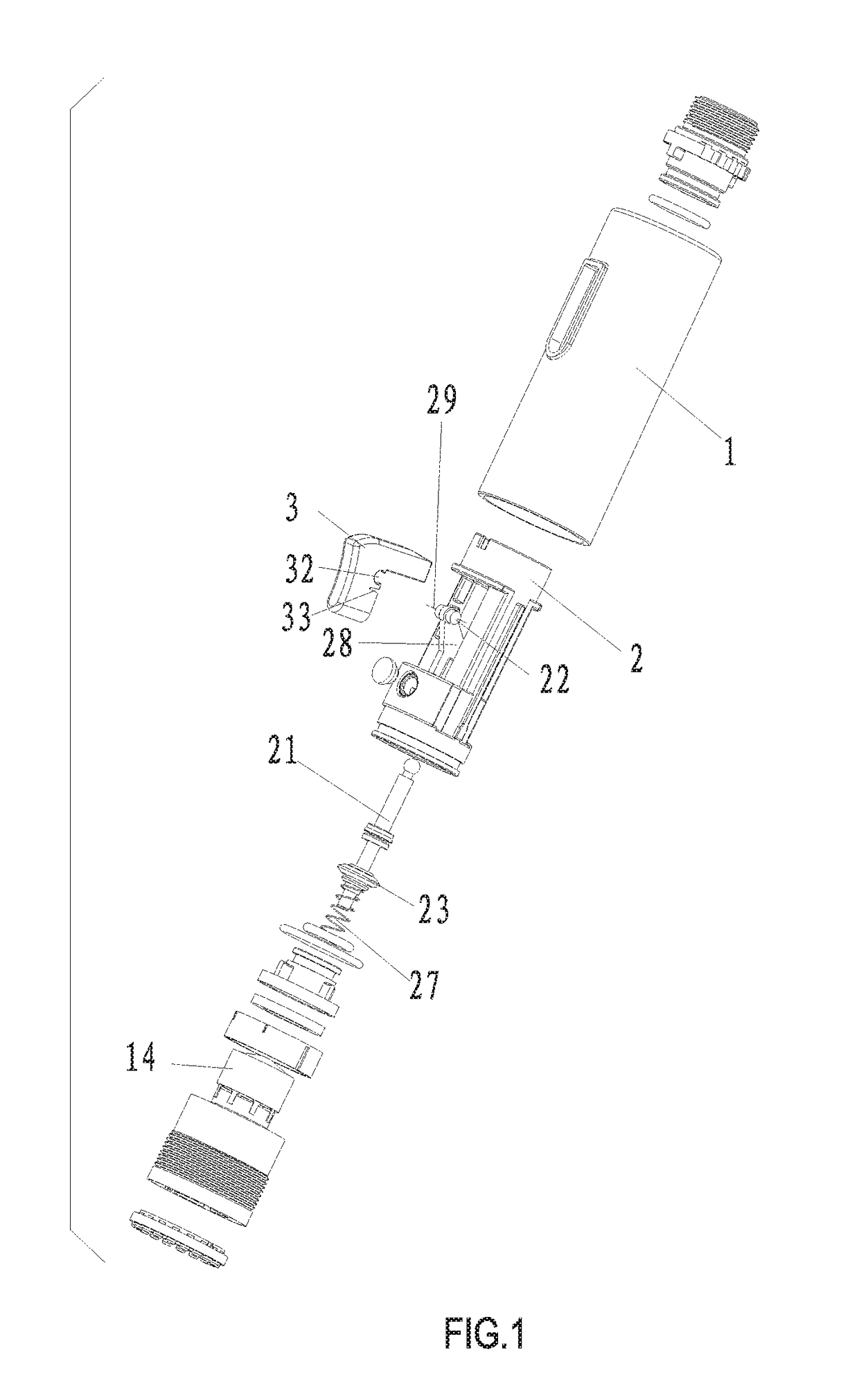
[0003]The present invention relates to a single button cyclic switch component, which achieves cyclic switching two water effects by one button, it is simple to assemble, it has stable structure and no idling happens during the operation.
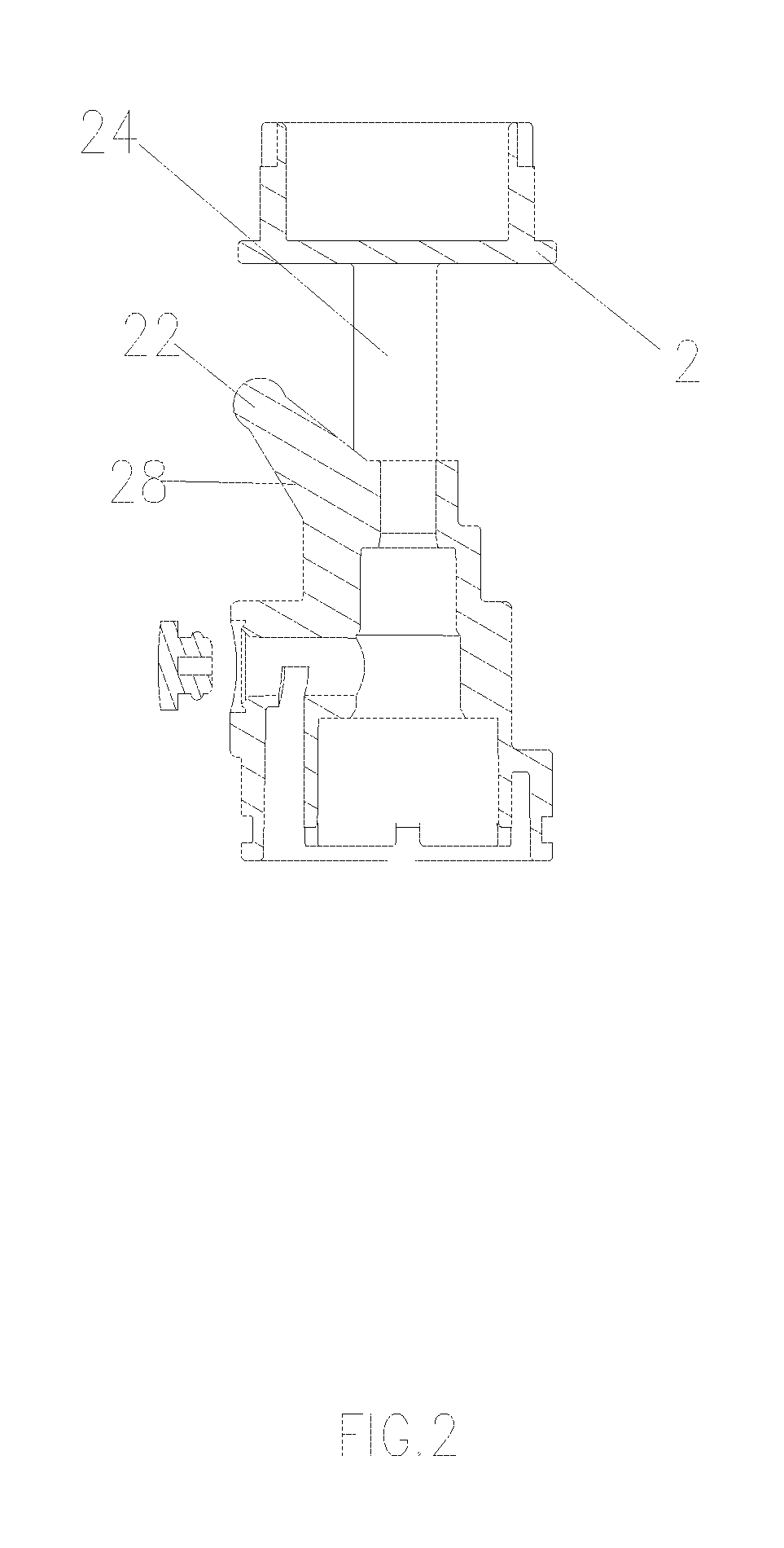
[0019]1. the single button cyclic switch component of the present invention has the reversing button movably coupled to the pivot, when pressing the reversing button down, the guiding groove of the end of the reversing button moves circularly about the pivot; so that the top end face of the guiding groove presses the reversing shaft, or the bottom end face of the guiding groove pushes the reversing shaft, therefore the reversing shaft moves upwardly or slides downwardly along the axis direction, so as to open the first outlet passage or the second outlet passage. It thus achieves cyclic switch, the assembly is simple, the structure is relatively stable so as to ensure long service time. In addition, as the guiding groove of the end of the button moves circularly about the pivot, the end of the reversing shaft is designed to be spherical, the guiding groove changes its position and acts on the end of the reversing shaft under the action of the button, so that no idling happens during the operation, it avoids the response delay of the switch, ensures the continuity of switching. In addition, as the water flows from the flowing passage through the hole then flows laterally into the accommodating chamber that is axially switching. It reduces the space of the structure in the radial direction, so that the diameter of the main body can be made smaller.
[0020]2. the single button cyclic switch component of the present invention is provided that, with the elastic element and the proper designation of the elastic force of the elastic element under pressure, when the water supply is turned off, the elastic element drives the reversing shaft to reset automatically. And as the directions of the elastic force and the water pressure on the sealing pad are opposite, it reduces the switch force of the user pressing the reversing button, it also improves the press hand feel of the user.
[0021]3. the single button cyclic switch component of the present invention is provided that, the reversing button is disposed with an elastic groove at the external side of the concave slot, the elastic groove is pressed or reset with the rotating coupling of the concave slot and the pivot, it improves the smooth degree of the coupling of the concave slot and the pivot, thus improving the hand feel.
[0022]4. the single button cyclic switch component of the present invention is provided that, the first outlet passage outflows bubble water, the second outlet passage outflows shower water, the shower head has two outlet modes that are usually used in a kitchen shower head. Furthermore, the default outlet state is bubble water, it improves the degree of humanization.BRIEF DESCRIPTION OF THE DRAWINGS

Problems solved by technology

In the kitchen, traditional faucets can not meet people's needs more.
However, the kitchen shower head has disadvantages: it feels hard when switched, it needs large force to switch the outlet mode.
The structure of the shower head would be unstable after long time's usage, large water pressure may damage the shower head.
On the other hand, the outlet mode switch structure is usually parallel to the radial direction of the housing, it restricts to the housing size in the radial direction, the housing can not be made small, thus making it unattractive in the appearance and unsuitable to the overall style.

Method used


Image

  • Single button, cyclic shower head switch
  • Single button, cyclic shower head switch
  • Single button, cyclic shower head switch

Examples


Embodiment Construction

[0028]The present invention will be further described with the drawings and the embodiments.

[0029]Referring to FIGS. 1-5, the single button cyclic switch component comprises:

[0030]a hollow main body 1 with a button opening 11; the main body 1 is disposed with a first outlet passage 12 and a second outlet passage 13; this embodiment takes two outlet passages for example, an outlet passage or more than two are available, they are simple substitutions, it would not further described hereafter.

[0031]A reversing shaft 21, the reversing shaft 21 is disposed in the main body 1 by a connecting element, the reversing shaft can move along the axis of the main body 1;

[0032]A reversing button 3, the reversing button 3 is movably coupled to the pivot 22 of the connecting element 2, the reversing button 3 is exposed out of the reversing button opening 11 so as to achieve the reversing button 3 switching between a first position and a second position; the reversing button 3 is disposed with a guid...


PUM


Abstract

A single button, cyclic shower head switch includes a main body having a button opening and at least two outlet passages; a reversing shaft disposed in the main body by a connecting element having a pivot, that has a sealing pad and one end having a spherical surface including a top face and a bottom face, and is configured to move along the axis of the main body; and a reversing button movably coupled to the pivot, that protrudes from the button opening, and is disposed with a guiding groove coupled to the spherical surface of the reversing shaft. When the reversing button is switched, the guiding groove moves circularly about the pivot and abuts against the spherical surface and causes the reversing shaft to move downwardly or upwardly along the axis of the main body so that the sealing pad closes one outlet passage and opens another outlet passage.

Description

FIELD OF THE INVENTION[0001]The present invention relates to an outlet switch component, especially to a single button cyclic switch component.BACKGROUND OF THE INVENTION[0002]In the kitchen, traditional faucets can not meet people's needs more. Traditional faucets have the outlet diversion, the outlet mode and the length fixed. To solve the problems, there are kitchen shower heads. A kitchen shower head can switch the outlet mode, the shower head can extend or withdraw as it is connected by a water pipe, the outlet direction of the shower head can be adjusted by the user, so that it is convenient to use. However, the kitchen shower head has disadvantages: it feels hard when switched, it needs large force to switch the outlet mode. The structure of the shower head would be unstable after long time's usage, large water pressure may damage the shower head. On the other hand, the outlet mode switch structure is usually parallel to the radial direction of the housing, it restricts to th...

Claims


Application Information

Patent Timeline
Patent Type & Authority Patents(United States)
IPC IPC(8): E03C1/02F16K31/528E03C1/04F16K11/044B05B1/18B05B1/16
CPCE03C1/0404F16K11/044F16K31/528E03C2001/0415B05B1/18E03C1/02E03C1/0405B05B1/1618F16K31/52416
Inventor WU, PENGFEIHU, YOUXIANWU, GANGQIANGCHEN, BIN
Owner XIAMEN SOLEX HIGH TECH IND CO LTD
Learn More