Difference measurement method for MEMS gyroscopes

A differential measurement, gyroscope technology, applied in the gyro effect for speed measurement, measuring device, speed/acceleration/shock measurement, etc.

Inactive Publication Date: 2008-04-09
BEIHANG UNIV
View PDF0 Cites 31 Cited by
  • Summary
  • Abstract
  • Description
  • Claims
  • Application Information

AI Technical Summary

Problems solved by technology

[0009] The purpose of the present invention is: to overcome the shortcomings of the existing method of measuring the rotational angular velocity of a certain shaft by using a single MEMS gyroscope, and provide a method for measuring the same rotational angular velocity and improving the measurement accuracy by using a difference measurement method of two MEMS gyroscopes

Method used


Image

  • Difference measurement method for MEMS gyroscopes
  • Difference measurement method for MEMS gyroscopes
  • Difference measurement method for MEMS gyroscopes

Examples


Embodiment Construction

[0087] The MEMS gyroscope in the first embodiment of the present invention takes the silicon MEMS gyroscope CRS03 as an example.

[0088] First, take a batch of silicon MEMS gyroscopes CRS03, 20 in this embodiment, and conduct test experiments according to the commonly used gyroscope test standards. Test and calibrate each important parameter of MEMS gyroscope, including various deterministic error items and their coefficients, usually including zero bias, zero bias stability, zero bias repeatability, scale factor, scale factor asymmetry, scale Factor repeatability, maximum input angular velocity, threshold, resolution, random walk coefficient, input axis misalignment angle, frequency bandwidth and other parameters.

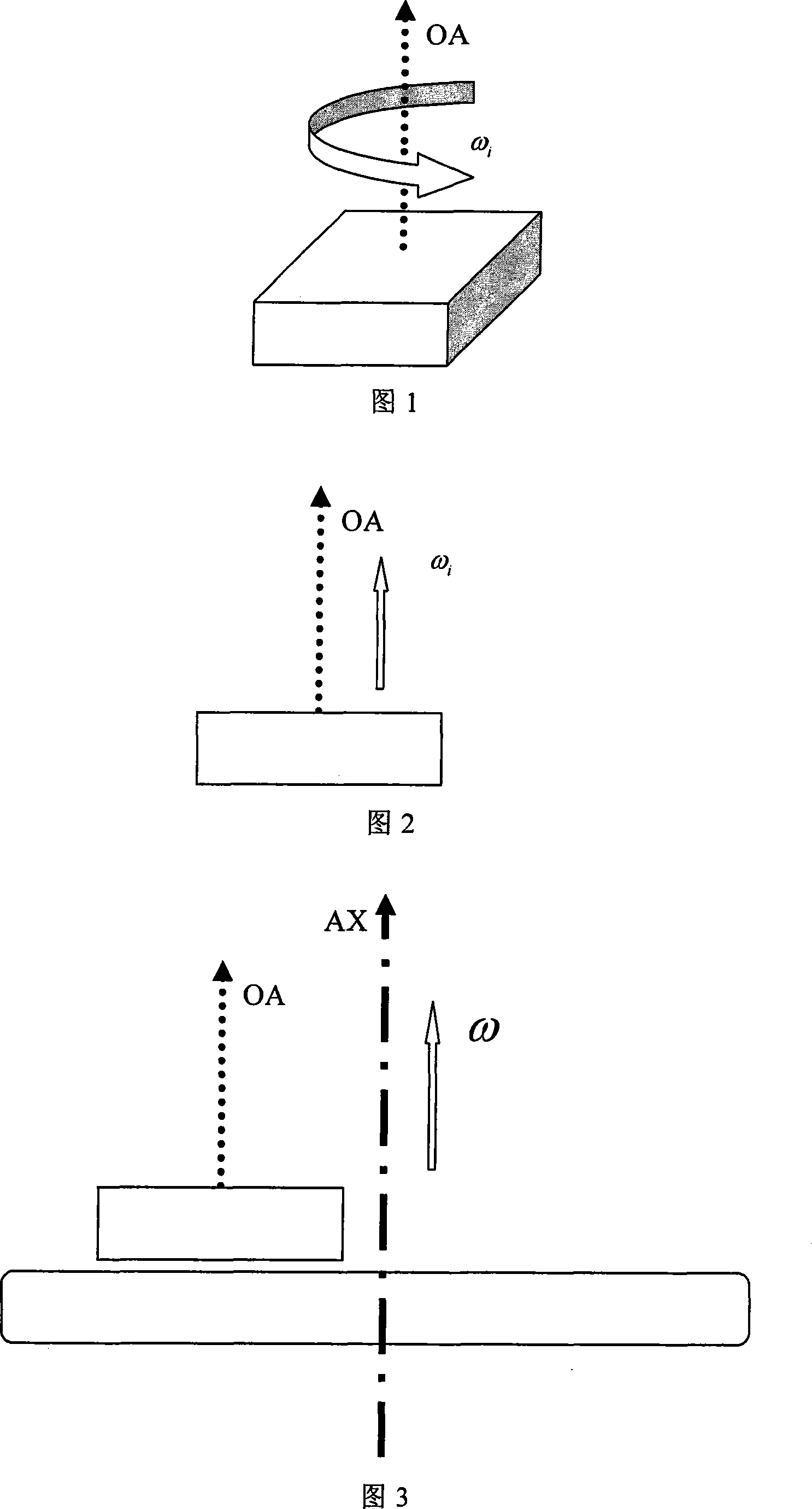
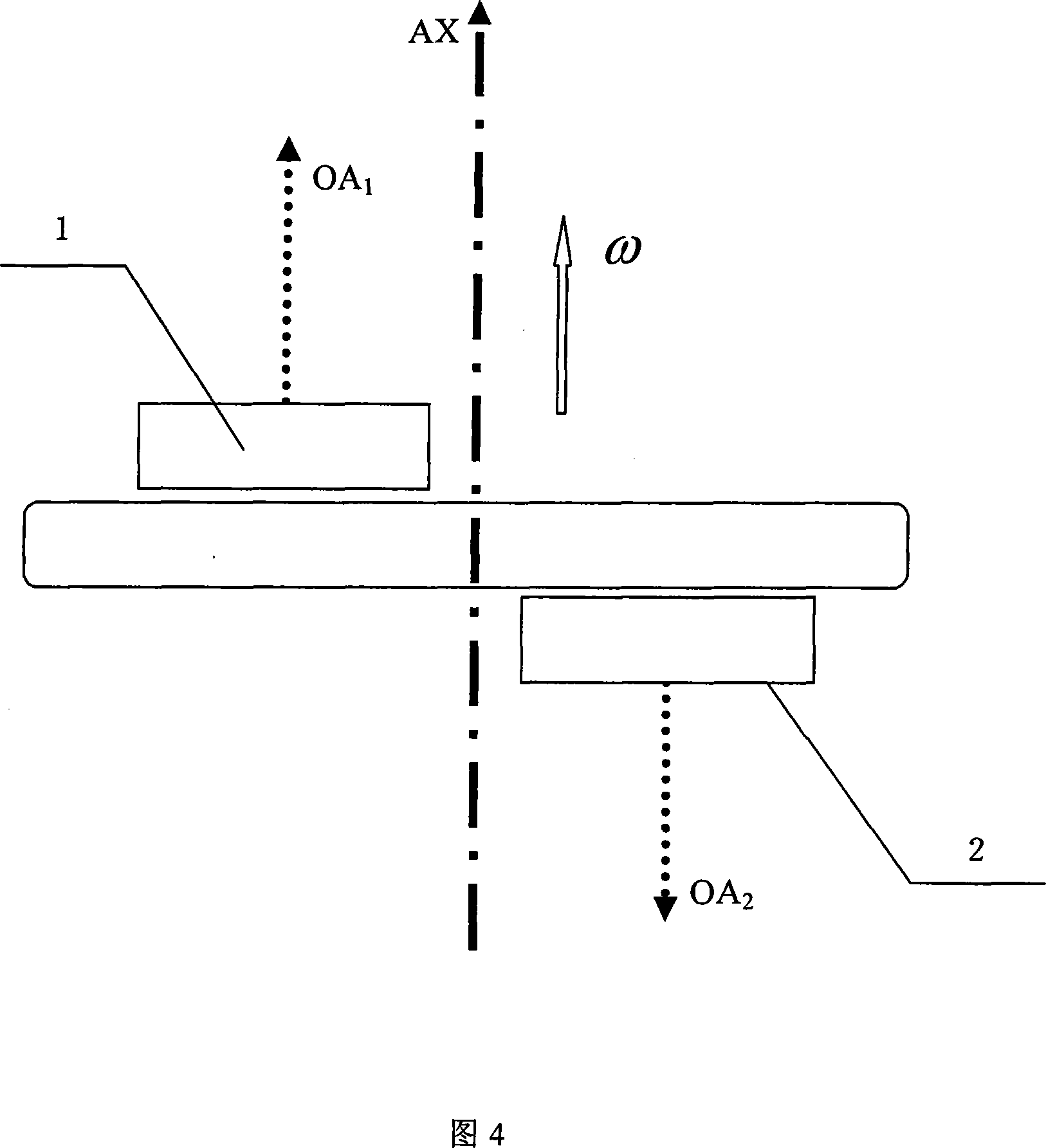
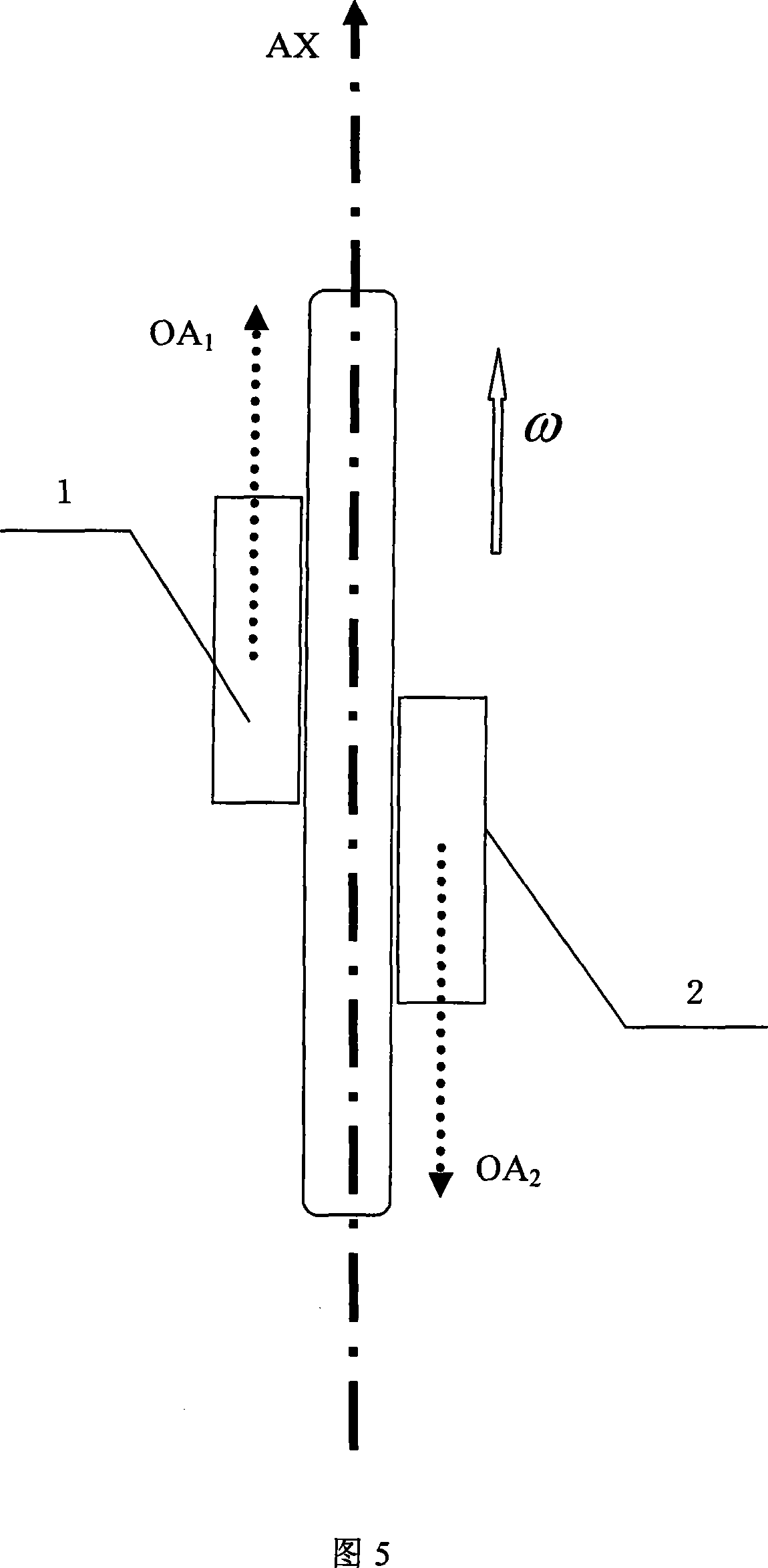
[0089] Secondly, divide this batch of MEMS gyroscopes CRS03 into two groups, 10 in each group. Turntable tests were performed using a uniaxial rate turntable. Fix the sensitive axis of one group of MEMS gyroscopes parallel to the rotation axis of the turntable ...


PUM


Abstract

The invention discloses a MEMS gyroscope difference measurement way. Two MEMS gyroscopes which are quite similar in environment sensitivity are selected out to form a gyroscope difference pair and angular velocity sensitive shafts of two MEMS gyroscopes are in opposite direction by installation, in parallel with a same tested drive shaft, and are sensitive to a same outside input angular velocity. Main parameters of two gyroscopes and an environmental coefficient ratio are determined through a test and a nominal test. When in practical application, the input angular velocity value of high precision is resolved according to an input angular velocity real-time solution formula. The invention selects out the gyroscopes of the same type and the same processing art, uses the similarity of response property to environment factors of the MEMS gyroscopes of the same models and property of suppression of output drift by difference installation and improves measuring precision of the MEMS gyroscopes through processing output data of the gyroscopes. The invention is suitable for application areas of various MEMS gyroscopes, in particular for situations of low requirement on production cost of the MEMS gyroscope and high precision of system output.

Description

technical field [0001] The invention belongs to the technical field of navigation, guidance and control, in particular to the application technology of MEMS vibrating gyroscopes, and is suitable for various low-cost, micro-miniature MEMS vibrating gyroscopes. Background technique [0002] Gyroscopes play an important role in many fields of science and technology. A gyroscope is a sensor for measuring angular velocity. Its schematic diagrams are shown in Figure 1 and Figure 2, where Figure 1 shows a three-dimensional schematic diagram of a gyroscope, and Figure 2 shows a schematic plan view of a gyroscope. The positive direction of its sensitive angular velocity is according to the right-handed spiral The principle is determined. The gyroscope can directly measure the external input angular velocity ω acting on its sensitive axis OA i , and can also indirectly measure the angle θ or angular acceleration β of its sensitive shaft through integral or differential operations. ...

Claims


Application Information

Patent Timeline
Patent Type & Authority Applications(China)
IPC IPC(8): G01C19/56G01C25/00G01C21/18G01P9/04G01P21/02B81B7/02
Inventor 房建成张海鹏冯浩楠蒋颜玮马艳武谭丽伟
Owner BEIHANG UNIV
Why Eureka
Try Eureka